From Wikipedia, the free encyclopedia
A linear actuator is a device that develops force and motion, from an available energy source, in a linear manner, as opposed to rotationally like an electric motor. There are various methods of achieving this linear motion. Several different examples are listed below.
Types of Linear Actuators
Mechanical actuators
Mechanical actuators typically convert rotary motion of a control knob or handle into linear displacement via screws and/or gears to which the knob or handle is attached. A jackscrew or car jack is a familiar mechanical actuator. Another family of actuators are based on the segmented spindle. Rotation of the jack handle is converted mechanically into the linear motion of the jack head. Mechanical actuators are also frequently used in the field of lasers and optics to manipulate the position of linear stages, rotary stages, mirror mounts, goniometers and other positioning instruments. For accurate and repeatable positioning, index marks may be used on control knobs. Some actuators even include an encoder and digital position readout.[1] These are similar to the adjustment knobs used on micrometers except that their purpose is position adjustment rather than position measurement.
Hydraulic actuators
Hydraulic actuators or hydraulic cylinders typically involve a hollow cylinder having a piston inserted in it. The two sides of the piston are alternately pressurized/de-pressurized to achieve controlled precise linear displacement of the piston and in turn the entity connected to the piston. The physical linear displacement is only along the axis of the piston/cylinder. This design is based on the principles of hydraulics. A familiar example of a manually operated hydraulic actuator is a hydraulic car jack. Typically though, the term "hydraulic actuator" refers to a device controlled by a hydraulic pump.
Piezoelectric actuators
The piezoelectric effect is a property of certain materials in which application of a voltage to the material causes it to expand. Very high voltages correspond to only tiny expansions. As a result, piezoelectric actuators can achieve extremely fine positioning resolution, but also have a very short range of motion. In addition, piezoelectric materials exhibit hysteresis which makes it difficult to control their expansion in a repeatable manner.
Electro-mechanical actuators
Electro-mechanical actuators are similar to mechanical actuators except that the control knob or handle is replaced with an electric motor. Rotary motion of the motor is converted to linear displacement of the actuator. There are many designs of modern linear actuators and every company that manufactures them tends to have their own proprietary method. The following is a generalized description of a very simple electro-mechanical linear actuator.
Simplified Design
Typically, a rotary driver (e.g. electric motor) is mechanically connected to a lead screw so that the rotation of the electric motor will make the lead screw rotate. A lead screw has a continuous helical thread machined on its circumference running along the length (similar to the thread on a bolt). Threaded onto the lead screw is a lead nut with corresponding helical threads. The nut is prevented from rotating with the lead screw (typically the nut interlocks with a non-rotating part of the actuator body). Therefore, when the lead screw is rotated, the nut will be driven along the threads. The direction of motion of the nut will depend on the direction of rotation of the lead screw. By connecting linkages to the nut, the motion can be converted to usable linear displacement. Most current actuators are built either for high speed, high force, or a compromise between the two. When considering an actuator for a particular application, the most important specifications are typically travel, speed, force, and lifetime.
Principles
In the majority of linear actuator designs, the basic principle of operation is that of an inclined plane. The threads of a lead screw act as a continuous ramp that allows a small rotational force to be used over a long distance to accomplish movement of a large load over a short distance.
Variations
Many variations on the basic design have been created. Most focus on providing general improvements such as a higher mechanical efficiency, speed, or load capacity. There is also a large engineering movement towards actuator miniaturization.
Most electro-mechanical designs incorporate a lead screw and lead nut. Some use a ball screw and ball nut. In either case the screw may be connected to a motor or manual control knob either directly or through a series of gears. Gears are typically used to allow a smaller (and weaker) motor spinning at a higher rpm to be geared down to provide the torque necessary to spin the screw under a heavier load than the motor would otherwise be capable of driving directly. Effectively this sacrifices actuator speed in favor of increased actuator thrust.
Some lead screws have multiple "starts". This means that they have multiple threads alternating on the same shaft. One way of visualizing this is in comparison to the multiple color stripes on a candy cane. This allows for more adjustment between thread pitch and nut/screw thread contact area, which determines the extension speed and load carrying capacity (of the threads), respectively.
Linear motors
A linear motor is essentially a rotary electric motor laid down on flat surface. Since the motor moves in a linear fashion to begin with, no lead screw is needed to convert rotary motion to linear. While high capacity is possible, the material and/or motor limitations on most designs are surpassed relatively quickly. Most linear motors have a relatively low load capacity compared to other types of linear actuators.
Wax motors
A wax motor typically uses an electric current to heat a block of wax causing it to expand. A plunger that bears on the wax is thus forced to move in a linear fashion.
Segmented spindles
KATAKA actuators consist of discrete chain elements which are interlinked to form a rod (the technology is known as the segmented spindle) thus making the actuator extremely compact (see www.kataka.dk).
Tuesday, August 19, 2008
Linear actuator
History Of Welding
Labels: History Of Welding, welding
The history of joining metals goes back several millennia, with the earliest examples of welding from the Bronze Age and the Iron Age in Europe and the Middle East. Welding was used in the construction of the Iron pillar in Delhi, India, erected about 310 and weighing 5.4 metric tons. The Middle Ages brought advances in forge welding, in which blacksmiths pounded heated metal repeatedly until bonding occurred. In 1540, Vannoccio Biringuccio published De la pirotechnia, which includes descriptions of the forging operation. Renaissance craftsmen were skilled in the process, and the industry continued to grow during the following centuries. Welding, however, was transformed during the 19th century—in 1800, Sir Humphry Davy discovered the electric arc, and advances in arc welding continued with the inventions of metal electrodes by a Russian, Nikolai Slavyanov, and an American, C. L. Coffin in the late 1800s, even as carbon arc welding, which used a carbon electrode, gained popularity. Around 1900, A. P. Strohmenger released a coated metal electrode in Britain, which gave a more stable arc, and in 1919, alternating current welding was invented by C. J. Holslag, but did not become popular for another decade.
Resistance welding was also developed during the final decades of the 19th century, with the first patents going to Elihu Thomson in 1885, who produced further advances over the next 15 years. Thermite welding was invented in 1893, and around that time, another process, oxyfuel welding, became well established. Acetylene was discovered in 1836 by Edmund Davy, but its use was not practical in welding until about 1900, when a suitable blowtorch was developed. At first, oxyfuel welding was one of the more popular welding methods due to its portability and relatively low cost. As the 20th century progressed, however, it fell out of favor for industrial applications. It was largely replaced with arc welding, as metal coverings (known as flux) for the electrode that stabilize the arc and shield the base material from impurities continued to be developed.
World War I caused a major surge in the use of welding processes, with the various military powers attempting to determine which of the several new welding processes would be best. The British primarily used arc welding, even constructing a ship, the Fulagar, with an entirely welded hull. Arc welding was first applied to aircraft during the war as well, as some German airplane fuselages were constructed using the process. Also noteworthy is the first welded road bridge in the world built across the river Słudwia Maurzyce near Łowicz, Poland) in 1929, but designed by Stefan Bryła of the Warsaw University of Technology in 1927.
During the 1920s, major advances were made in welding technology, including the introduction of automatic welding in 1920, in which electrode wire was fed continuously. Shielding gas became a subject receiving much attention, as scientists attempted to protect welds from the effects of oxygen and nitrogen in the atmosphere. Porosity and brittleness were the primary problems, and the solutions that developed included the use of hydrogen, argon, and helium as welding atmospheres. During the following decade, further advances allowed for the welding of reactive metals like aluminum and magnesium. This, in conjunction with developments in automatic welding, alternating current, and fluxes fed a major expansion of arc welding during the 1930s and then during World War II.
During the middle of the century, many new welding methods were invented. 1930 saw the release of stud welding, which soon became popular in shipbuilding and construction. Submerged arc welding was invented the same year, and continues to be popular today. Gas tungsten arc welding, after decades of development, was finally perfected in 1941, and gas metal arc welding followed in 1948, allowing for fast welding of non-ferrous materials but requiring expensive shielding gases. Shielded metal arc welding was developed during the 1950s, using a flux coated consumable electrode, and it quickly became the most popular metal arc welding process. In 1957, the flux-cored arc welding process debuted, in which the self-shielded wire electrode could be used with automatic equipment, resulting in greatly increased welding speeds, and that same year, plasma arc welding was invented. Electroslag welding was introduced in 1958, and it was followed by its cousin, electrogas welding, in 1961.
Other recent developments in welding include the 1958 breakthrough of electron beam welding, making deep and narrow welding possible through the concentrated heat source. Following the invention of the laser in 1960, laser beam welding debuted several decades later, and has proved to be especially useful in high-speed, automated welding. Both of these processes, however, continue to be quite expensive due the high cost of the necessary equipment, and this has limited their applications.
Processes
Arc welding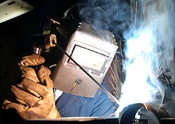
These processes use a welding power supply to create and maintain an electric arc between an electrode and the base material to melt metals at the welding point. They can use either direct (DC) or alternating (AC) current, and consumable or non-consumable electrodes. The welding region is sometimes protected by some type of inert or semi-inert gas, known as a shielding gas, and filler material is sometimes used as well.
Power supplies
To supply the electrical energy necessary for arc welding processes, a number of different power supplies can be used. The most common classification is constant current power supplies and constant voltage power supplies. In arc welding, the length of the arc is directly related to the voltage, and the amount of heat input is related to the current. Constant current power supplies are most often used for manual welding processes such as gas tungsten arc welding and shielded metal arc welding, because they maintain a relatively constant current even as the voltage varies. This is important because in manual welding, it can be difficult to hold the electrode perfectly steady, and as a result, the arc length and thus voltage tend to fluctuate. Constant voltage power supplies hold the voltage constant and vary the current, and as a result, are most often used for automated welding processes such as gas metal arc welding, flux cored arc welding, and submerged arc welding. In these processes, arc length is kept constant, since any fluctuation in the distance between the wire and the base material is quickly rectified by a large change in current. For example, if the wire and the base material get too close, the current will rapidly increase, which in turn causes the heat to increase and the tip of the wire to melt, returning it to its original separation distance.
The type of current used in arc welding also plays an important role in welding. Consumable electrode processes such as shielded metal arc welding and gas metal arc welding generally use direct current, but the electrode can be charged either positively or negatively. In welding, the positively charged anode will have a greater heat concentration, and as a result, changing the polarity of the electrode has an impact on weld properties. If the electrode is positively charged, the base metal will be hotter, increasing weld penetration and welding speed. Alternatively, a negatively charged electrode results in more shallow welds. Nonconsumable electrode processes, such as gas tungsten arc welding, can use either type of direct current, as well as alternating current. However, with direct current, because the electrode only creates the arc and does not provide filler material, a positively charged electrode causes shallow welds, while a negatively charged electrode makes deeper welds. Alternating current rapidly moves between these two, resulting in medium-penetration welds. One disadvantage of AC, the fact that the arc must be re-ignited after every zero crossing, has been addressed with the invention of special power units that produce a square wave pattern instead of the normal sine wave, making rapid zero crossings possible and minimizing the effects of the problem.
Processes
Shielded metal arc welding
One of the most common types of arc welding is shielded metal arc welding (SMAW), which is also known as manual metal arc welding (MMA) or stick welding. Electric current is used to strike an arc between the base material and consumable electrode rod, which is made of steel and is covered with a flux that protects the weld area from oxidation and contamination by producing CO2 gas during the welding process. The electrode core itself acts as filler material, making a separate filler unnecessary.
The process is versatile and can be performed with relatively inexpensive equipment, making it well suited to shop jobs and field work. An operator can become reasonably proficient with a modest amount of training and can achieve mastery with experience. Weld times are rather slow, since the consumable electrodes must be frequently replaced and because slag, the residue from the flux, must be chipped away after welding. Furthermore, the process is generally limited to welding ferrous materials, though special electrodes have made possible the welding of cast iron, nickel, aluminium, copper, and other metals. Inexperienced operators may find it difficult to make good out-of-position welds with this process.
Gas metal arc welding (GMAW), also known as metal inert gas or MIG welding, is a semi-automatic or automatic process that uses a continuous wire feed as an electrode and an inert or semi-inert gas mixture to protect the weld from contamination. As with SMAW, reasonable operator proficiency can be achieved with modest training. Since the electrode is continuous, welding speeds are greater for GMAW than for SMAW. Also, the smaller arc size compared to the shielded metal arc welding process makes it easier to make out-of-position welds (e.g., overhead joints, as would be welded underneath a structure).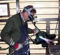
The equipment required to perform the GMAW process is more complex and expensive than that required for SMAW, and requires a more complex setup procedure. Therefore, GMAW is less portable and versatile, and due to the use of a separate shielding gas, is not particularly suitable for outdoor work. However, owing to the higher average rate at which welds can be completed, GMAW is well suited to production welding. The process can be applied to a wide variety of metals, both ferrous and non-ferrous.
A related process, flux-cored arc welding (FCAW), uses similar equipment but uses wire consisting of a steel electrode surrounding a powder fill material. This cored wire is more expensive than the standard solid wire and can generate fumes and/or slag, but it permits even higher welding speed and greater metal penetration.
Gas tungsten arc welding (GTAW), or tungsten inert gas (TIG) welding (also sometimes erroneously referred to as heliarc welding), is a manual welding process that uses a nonconsumable tungsten electrode, an inert or semi-inert gas mixture, and a separate filler material. Especially useful for welding thin materials, this method is characterized by a stable arc and high quality welds, but it requires significant operator skill and can only be accomplished at relatively low speeds.
GTAW can be used on nearly all weldable metals, though it is most often applied to stainless steel and light metals. It is often used when quality welds are extremely important, such as in bicycle, aircraft and naval applications. A related process, plasma arc welding, also uses a tungsten electrode but uses plasma gas to make the arc. The arc is more concentrated than the GTAW arc, making transverse control more critical and thus generally restricting the technique to a mechanized process. Because of its stable current, the method can be used on a wider range of material thicknesses than can the GTAW process, and furthermore, it is much faster. It can be applied to all of the same materials as GTAW except magnesium, and automated welding of stainless steel is one important application of the process. A variation of the process is plasma cutting, an efficient steel cutting process.
Submerged arc welding (SAW) is a high-productivity welding method in which the arc is struck beneath a covering layer of flux. This increases arc quality, since contaminants in the atmosphere are blocked by the flux. The slag that forms on the weld generally comes off by itself, and combined with the use of a continuous wire feed, the weld deposition rate is high. Working conditions are much improved over other arc welding processes, since the flux hides the arc and almost no smoke is produced. The process is commonly used in industry, especially for large products and in the manufacture of welded pressure vessels. Other arc welding processes include atomic hydrogen welding, carbon arc welding, electroslag welding, electrogas welding, and stud arc welding.
Gas welding a steel armature using the oxy-acetylene process.
Gas welding a steel armature using the oxy-acetylene process.
Gas
The most common gas welding process is oxyfuel welding, also known as oxyacetylene welding. It is one of the oldest and most versatile welding processes, but in recent years it has become less popular in industrial applications. It is still widely used for welding pipes and tubes, as well as repair work. It is also frequently well-suited, and favored, for fabricating some types of metal-based artwork. Oxyfuel equipment is versatile, lending itself not only to some sorts of iron or steel welding but also to brazing, braze-welding, metal heating (for bending and forming), and also oxyfuel cutting.
The equipment is relatively inexpensive and simple, generally employing the combustion of acetylene in oxygen to produce a welding flame temperature of about 3100 °C. The flame, since it is less concentrated than an electric arc, causes slower weld cooling, which can lead to greater residual stresses and weld distortion, though it eases the welding of high alloy steels. A similar process, generally called oxyfuel cutting, is used to cut metals.[23] Other gas welding methods, such as air acetylene welding, oxygen hydrogen welding, and pressure gas welding are quite similar, generally differing only in the type of gases used. A water torch is sometimes used for precision welding of small items such as jewelry. Gas welding is also used in plastic welding, though the heated substance is air, and the temperatures are much lower.
Resistance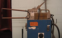
Resistance welding involves the generation of heat by passing current through the resistance caused by the contact between two or more metal surfaces. Small pools of molten metal are formed at the weld area as high current (1000–100,000 A) is passed through the metal. In general, resistance welding methods are efficient and cause little pollution, but their applications are somewhat limited and the equipment cost can be high.
Spot welding is a popular resistance welding method used to join overlapping metal sheets of up to 3 mm thick. Two electrodes are simultaneously used to clamp the metal sheets together and to pass current through the sheets. The advantages of the method include efficient energy use, limited workpiece deformation, high production rates, easy automation, and no required filler materials. Weld strength is significantly lower than with other welding methods, making the process suitable for only certain applications. It is used extensively in the automotive industry—ordinary cars can have several thousand spot welds made by industrial robots. A specialized process, called shot welding, can be used to spot weld stainless steel.
Like spot welding, seam welding relies on two electrodes to apply pressure and current to join metal sheets. However, instead of pointed electrodes, wheel-shaped electrodes roll along and often feed the workpiece, making it possible to make long continuous welds. In the past, this process was used in the manufacture of beverage cans, but now its uses are more limited. Other resistance welding methods include flash welding, projection welding, and upset welding.
Energy beam
Energy beam welding methods, namely laser beam welding and electron beam welding, are relatively new processes that have become quite popular in high production applications. The two processes are quite similar, differing most notably in their source of power. Laser beam welding employs a highly focused laser beam, while electron beam welding is done in a vacuum and uses an electron beam. Both have a very high energy density, making deep weld penetration possible and minimizing the size of the weld area. Both processes are extremely fast, and are easily automated, making them highly productive. The primary disadvantages are their very high equipment costs (though these are decreasing) and a susceptibility to thermal cracking. Developments in this area include laser-hybrid welding, which uses principles from both laser beam welding and arc welding for even better weld properties.
Solid-state
Like the first welding process, forge welding, some modern welding methods do not involve the melting of the materials being joined. One of the most popular, ultrasonic welding, is used to connect thin sheets or wires made of metal or thermoplastic by vibrating them at high frequency and under high pressure. The equipment and methods involved are similar to that of resistance welding, but instead of electric current, vibration provides energy input. Welding metals with this process does not involve melting the materials; instead, the weld is formed by introducing mechanical vibrations horizontally under pressure. When welding plastics, the materials should have similar melting temperatures, and the vibrations are introduced vertically. Ultrasonic welding is commonly used for making electrical connections out of aluminum or copper, and it is also a very common polymer welding process.
Another common process, explosion welding, involves the joining of materials by pushing them together under extremely high pressure. The energy from the impact plasticizes the materials, forming a weld, even though only a limited amount of heat is generated. The process is commonly used for welding dissimilar materials, such as the welding of aluminum with steel in ship hulls or compound plates. Other solid-state welding processes include co-extrusion welding, cold welding, diffusion welding, friction welding (including friction stir welding), high frequency welding, hot pressure welding, induction welding, and roll welding.
Geometry
Common welding joint types – (1) Square butt joint, (2) Single-V preparation joint, (3) Lap joint, (4) T-joint.
Common welding joint types – (1) Square butt joint, (2) Single-V preparation joint, (3) Lap joint, (4) T-joint.
Welds can be geometrically prepared in many different ways. The five basic types of weld joints are the butt joint, lap joint, corner joint, edge joint, and T-joint. Other variations exist as well—for example, double-V preparation joints are characterized by the two pieces of material each tapering to a single center point at one-half their height. Single-U and double-U preparation joints are also fairly common—instead of having straight edges like the single-V and double-V preparation joints, they are curved, forming the shape of a U. Lap joints are also commonly more than two pieces thick—depending on the process used and the thickness of the material, many pieces can be welded together in a lap joint geometry.
Often, particular joint designs are used exclusively or almost exclusively by certain welding processes. For example, resistance spot welding, laser beam welding, and electron beam welding are most frequently performed on lap joints. However, some welding methods, like shielded metal arc welding, are extremely versatile and can weld virtually any type of joint. Additionally, some processes can be used to make multipass welds, in which one weld is allowed to cool, and then another weld is performed on top of it. This allows for the welding of thick sections arranged in a single-V preparation joint, for example.
The cross-section of a welded butt joint, with the darkest gray representing the weld or fusion zone, the medium gray the heat-affected zone, and the lightest gray the base material.
The cross-section of a welded butt joint, with the darkest gray representing the weld or fusion zone, the medium gray the heat-affected zone, and the lightest gray the base material.
After welding, a number of distinct regions can be identified in the weld area. The weld itself is called the fusion zone—more specifically, it is where the filler metal was laid during the welding process. The properties of the fusion zone depend primarily on the filler metal used, and its compatibility with the base materials. It is surrounded by the heat-affected zone, the area that had its microstructure and properties altered by the weld. These properties depend on the base material's behavior when subjected to heat. The metal in this area is often weaker than both the base material and the fusion zone, and is also where residual stresses are found.
Quality
Most often, the major metric used for judging the quality of a weld is its strength and the strength of the material around it. Many distinct factors influence this, including the welding method, the amount and concentration of energy input, the base material, the filler material, the flux material, the design of the joint, and the interactions between all these factors. To test the quality of a weld, either destructive or nondestructive testing methods are commonly used to verify that welds are defect-free, have acceptable levels of residual stresses and distortion, and have acceptable heat-affected zone (HAZ) properties. Welding codes and specifications exist to guide welders in proper welding technique and in how to judge the quality of welds.
Heat-affected zone
The blue area results from oxidation at a corresponding temperature of 600 °F (316 °C). This is an accurate way to identify temperature, but does not represent the HAZ width. The HAZ is the narrow area that immediately surrounds the welded base metal.
The blue area results from oxidation at a corresponding temperature of 600 °F (316 °C). This is an accurate way to identify temperature, but does not represent the HAZ width. The HAZ is the narrow area that immediately surrounds the welded base metal.
The effects of welding on the material surrounding the weld can be detrimental—depending on the materials used and the heat input of the welding process used, the HAZ can be of varying size and strength. The thermal diffusivity of the base material plays a large role—if the diffusivity is high, the material cooling rate is high and the HAZ is relatively small. Conversely, a low diffusivity leads to slower cooling and a larger HAZ. The amount of heat injected by the welding process plays an important role as well, as processes like oxyacetylene welding have an unconcentrated heat input and increase the size of the HAZ. Processes like laser beam welding give a highly concentrated, limited amount of heat, resulting in a small HAZ. Arc welding falls between these two extremes, with the individual processes varying somewhat in heat input.[30][31] To calculate the heat input for arc welding procedures, the following formula can be used:
Q = \left(\frac{V \times I \times 60}{S \times 1000} \right) \times \mathit{Efficiency}
where Q = heat input (kJ/mm), V = voltage (V), I = current (A), and S = welding speed (mm/min). The efficiency is dependent on the welding process used, with shielded metal arc welding having a value of 0.75, gas metal arc welding and submerged arc welding, 0.9, and gas tungsten arc welding, 0.8.
Distortion and cracking
http://upload.wikimedia.org/wikipedia/commons/thumb/2/21/Pipe_root_weld_with_HAZ.jpg/200px-Pipe_root_weld_with_HAZ.jpg
Welding methods that involve the melting of metal at the site of the joint necessarily are prone to shrinkage as the heated metal cools. Shrinkage, in turn, can introduce residual stresses and both longitudinal and rotational distortion. Distortion can pose a major problem, since the final product is not the desired shape. To alleviate rotational distortion, the workpieces can be offset, so that the welding results in a correctly shaped piece. Other methods of limiting distortion, such as clamping the workpieces in place, cause the buildup of residual stress in the heat-affected zone of the base material. These stresses can reduce the strength of the base material, and can lead to catastrophic failure through cold cracking, as in the case of several of the Liberty ships. Cold cracking is limited to steels, and is associated with the formation of martensite as the weld cools. The cracking occurs in the heat-affected zone of the base material. To reduce the amount of distortion and residual stresses, the amount of heat input should be limited, and the welding sequence used should not be from one end directly to the other, but rather in segments. The other type of cracking, hot cracking or solidification cracking, can occur with all metals, and happens in the fusion zone of a weld. To diminish the probability of this type of cracking, excess material restraint should be avoided, and a proper filler material should be utilized.
Weldability
The quality of a weld is also dependent on the combination of materials used for the base material and the filler material. Not all metals are suitable for welding, and not all filler metals work well with acceptable base materials.
Steels
The weldability of steels is inversely proportional to a property known as the hardenability of the steel, which measures the probability of forming martensite during welding or heat treatment. The hardenability of steel depends on its chemical composition, with greater quantities of carbon and other alloying elements resulting in a higher hardenability and thus a lower weldability. In order to be able to judge alloys made up of many distinct materials, a measure known as the equivalent carbon content is used to compare the relative weldabilities of different alloys by comparing their properties to a plain carbon steel. The effect on weldability of elements like chromium and vanadium, while not as great as carbon, is more significant than that of copper and nickel, for example. As the equivalent carbon content rises, the weldability of the alloy decreases. The disadvantage to using plain carbon and low-alloy steels is their lower strength—there is a trade-off between material strength and weldability. High strength, low-alloy steels were developed especially for welding applications during the 1970s, and these generally easy to weld materials have good strength, making them ideal for many welding applications.
Stainless steels, because of their high chromium content, tend to behave differently with respect to weldability than other steels. Austenitic grades of stainless steels tend to be the most weldable, but they are especially susceptible to distortion due to their high coefficient of thermal expansion. Some alloys of this type are prone to cracking and reduced corrosion resistance as well. Hot cracking is possible if the amount of ferrite in the weld is not controlled—to alleviate the problem, an electrode is used that deposits a weld metal containing a small amount of ferrite. Other types of stainless steels, such as ferritic and martensitic stainless steels, are not as easily welded, and must often be preheated and welded with special electrodes.
Aluminum
The weldability of aluminum alloys varies significantly, depending on the chemical composition of the alloy used. Aluminum alloys are susceptible to hot cracking, and to combat the problem, welders increase the welding speed to lower the heat input. Preheating reduces the temperature gradient across the weld zone and thus helps reduce hot cracking, but it can reduce the mechanical properties of the base material and should not be used when the base material is restrained. The design of the joint can be changed as well, and a more compatible filler alloy can be selected to decrease the likelihood of hot cracking. Aluminum alloys should also be cleaned prior to welding, with the goal of removing all oxides, oils, and loose particles from the surface to be welded. This is especially important because of an aluminum weld's susceptibility to porosity due to hydrogen and dross due to oxygen.
Unusual conditions
Underwater welding
While many welding applications are done in controlled environments such as factories and repair shops, some welding processes are commonly used in a wide variety of conditions, such as open air, underwater, and vacuums (such as space). In open-air applications, such as construction and outdoors repair, shielded metal arc welding is the most common process. Processes that employ inert gases to protect the weld cannot be readily used in such situations, because unpredictable atmospheric movements can result in a faulty weld. Shielded metal arc welding is also often used in underwater welding in the construction and repair of ships, offshore platforms, and pipelines, but others, such as flux cored arc welding and gas tungsten arc welding, are also common. Welding in space is also possible—it was first attempted in 1969 by Russian cosmonauts, when they performed experiments to test shielded metal arc welding, plasma arc welding, and electron beam welding in a depressurized environment. Further testing of these methods was done in the following decades, and today researchers continue to develop methods for using other welding processes in space, such as laser beam welding, resistance welding, and friction welding. Advances in these areas could prove indispensable for projects like the construction of the International Space Station, which will likely rely heavily on welding for joining in space the parts that were manufactured on Earth.
Safety issues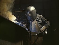
Arc welding with a welding helmet, gloves, and other protective clothing.
Welding, without the proper precautions, can be a dangerous and unhealthy practice. However, with the use of new technology and proper protection, risks of injury and death associated with welding can be greatly reduced. Because many common welding procedures involve an open electric arc or flame, the risk of burns is significant. To prevent them, welders wear personal protective equipment in the form of heavy leather gloves and protective long sleeve jackets to avoid exposure to extreme heat and flames. Additionally, the brightness of the weld area leads to a condition called arc eye in which ultraviolet light causes inflammation of the cornea and can burn the retinas of the eyes. Goggles and welding helmets with dark face plates are worn to prevent this exposure, and in recent years, new helmet models have been produced that feature a face plate that self-darkens upon exposure to high amounts of UV light. To protect bystanders, translucent welding curtains often surround the welding area. These curtains, made of a polyvinyl chloride plastic film, shield nearby workers from exposure to the UV light from the electric arc, but should not be used to replace the filter glass used in helmets.
Welders are also often exposed to dangerous gases and particulate matter. Processes like flux-cored arc welding and shielded metal arc welding produce smoke containing particles of various types of oxides, which in some cases can lead to medical conditions like metal fume fever. The size of the particles in question tends to influence the toxicity of the fumes, with smaller particles presenting a greater danger. Additionally, many processes produce fumes and various gases, most commonly carbon dioxide, ozone and heavy metals, that can prove dangerous without proper ventilation and training. Furthermore, because the use of compressed gases and flames in many welding processes poses an explosion and fire risk, some common precautions include limiting the amount of oxygen in the air and keeping combustible materials away from the workplace. Welding fume extractors are often used to remove the fume from the source and filter the fumes through a HEPA filter.
Costs and trends
As an industrial process, the cost of welding plays a crucial role in manufacturing decisions. Many different variables affect the total cost, including equipment cost, labor cost, material cost, and energy cost. Depending on the process, equipment cost can vary, from inexpensive for methods like shielded metal arc welding and oxyfuel welding, to extremely expensive for methods like laser beam welding and electron beam welding. Because of their high cost, they are only used in high production operations. Similarly, because automation and robots increase equipment costs, they are only implemented when high production is necessary. Labor cost depends on the deposition rate (the rate of welding), the hourly wage, and the total operation time, including both time welding and handling the part. The cost of materials includes the cost of the base and filler material, and the cost of shielding gases. Finally, energy cost depends on arc time and welding power demand.
For manual welding methods, labor costs generally make up the vast majority of the total cost. As a result, many cost-savings measures are focused on minimizing the operation time. To do this, welding procedures with high deposition rates can be selected, and weld parameters can be fine-tuned to increase welding speed. Mechanization and automatization are often implemented to reduce labor costs, but this frequently increases the cost of equipment and creates additional setup time. Material costs tend to increase when special properties are necessary, and energy costs normally do not amount to more than several percent of the total welding cost.
In recent years, in order to minimize labor costs in high production manufacturing, industrial welding has become increasingly more automated, most notably with the use of robots in resistance spot welding (especially in the automotive industry) and in arc welding. In robot welding, mechanized devices both hold the material and perform the weld, and at first, spot welding was its most common application. But robotic arc welding has been increasing in popularity as technology has advanced. Other key areas of research and development include the welding of dissimilar materials (such as steel and aluminum, for example) and new welding processes, such as friction stir, magnetic pulse, conductive heat seam, and laser-hybrid welding. Furthermore, progress is desired in making more specialized methods like laser beam welding practical for more applications, such as in the aerospace and automotive industries. Researchers also hope to better understand the often unpredictable properties of welds, especially microstructure, residual stresses, and a weld's tendency to crack or deform.
Welding
Labels: welding
From Wikipedia, the free encyclopedia
Welding is a fabrication process that joins materials, usually metals or thermoplastics, by causing coalescence. This is often done by melting the workpieces and adding a filler material to form a pool of molten material (the weld puddle) that cools to become a strong joint, with pressure sometimes used in conjunction with heat, or by itself, to produce the weld. This is in contrast with soldering and brazing, which involve melting a lower-melting-point material between the workpieces to form a bond between them, without melting the workpieces.
Many different energy sources can be used for welding, including a gas flame, an electric arc, a laser, an electron beam, friction, and ultrasound. While often an industrial process, welding can be done in many different environments, including open air, underwater and in outer space. Regardless of location, however, welding remains dangerous, and precautions must be taken to avoid burns, electric shock, eye damage, poisonous fumes, and overexposure to ultraviolet light.
Until the end of the 19th century, the only welding process was forge welding, which blacksmiths had used for centuries to join metals by heating and pounding them. Arc welding and oxyfuel welding were among the first processes to develop late in the century, and resistance welding followed soon after. Welding technology advanced quickly during the early 20th century as World War I and World War II drove the demand for reliable and inexpensive joining methods. Following the wars, several modern welding techniques were developed, including manual methods like shielded metal arc welding, now one of the most popular welding methods, as well as semi-automatic and automatic processes such as gas metal arc welding, submerged arc welding, flux-cored arc welding and electroslag welding. Developments continued with the invention of laser beam welding and electron beam welding in the latter half of the century. Today, the science continues to advance. Robot welding is becoming more commonplace in industrial settings, and researchers continue to develop new welding methods and gain greater understanding of weld quality and properties.
Computer-Aided Design
From Wikipedia, the free encyclopedia
"CADD" and "CAD" redirect here. For other uses, see CADD (disambiguation) and CAD (disambiguation).
"ECAD" redirects here. For other uses, see ECAD (disambiguation).
Computer-aided design CAD is the use of computer technology to aid in the design and especially the drafting (technical drawing and engineering drawing) of a part or product, including entire buildings. It is both a visual (or drawing) and symbol-based method of communication whose conventions are particular to a specific technical field.
Drafting can be done in two dimensions ("2D") and three dimensions ("3D").
Drafting is the integral communication of technical or engineering drawings and is the industrial arts sub-discipline that underlies all involved technical endeavors. In representing complex, three-dimensional objects in two-dimensional drawings, these objects have traditionally been represented by three projected views at right angles.
Current CAD software packages range from 2D vector-based drafting systems to 3D solid and surface modellers. Modern CAD packages can also frequently allow rotations in three dimensions, allowing viewing of a designed object from any desired angle, even from the inside looking out. Some CAD software is capable of dynamic mathematic modeling, in which case it may be marketed as CADD — computer-aided design and drafting.
CAD is used in the design of tools and machinery used in the manufacture of components, and in the drafting and design of all types of buildings, from small residential types (houses) to the largest commercial and industrial structures (hospitals and factories).
CAD is mainly used for detailed engineering of 3D models and/or 2D drawings of physical components, but it is also used throughout the engineering process from conceptual design and layout of products, through strength and dynamic analysis of assemblies to definition of manufacturing methods of components.
CAD has become an especially important technology within the scope of computer-aided technologies, with benefits such as lower product development costs and a greatly shortened design cycle. CAD enables designers to lay out and develop work on screen, print it out and save it for future editing, saving time on their drawings.
History
Designers have long used computers for their calculations. Initial developments were carried out in the 1960s within the aircraft and automotive industries in the area of 3D surface construction and NC programming, most of it independent of one another and often not publicly published until much later. Some of the mathematical description work on curves was developed in the early 1940s by Robert Issac Newton from Pawtucket, Rhode Island. Robert A. Heinlein in his 1957 novel The Door into Summer suggested the possibility of a robotic Drafting Dan. However, probably the most important work on polynomial curves and sculptured surface was done by Pierre Bezier (Renault), Paul de Casteljau (Citroen), Steven Anson Coons (MIT, Ford), James Ferguson (Boeing), Carl de Boor (GM), Birkhoff (GM) and Garibedian (GM) in the 1960s and W. Gordon (GM) and R. Riesenfeld in the 1970s.
It is argued that a turning point was the development of the SKETCHPAD system at MIT in 1963 by Ivan Sutherland (who later created a graphics technology company with Dr. David Evans). The distinctive feature of SKETCHPAD was that it allowed the designer to interact with his computer graphically: the design can be fed into the computer by drawing on a CRT monitor with a light pen. Effectively, it was a prototype of graphical user interface, an indispensable feature of modern CAD.
The first commercial applications of CAD were in large companies in the automotive and aerospace industries, as well as in electronics. Only large corporations could afford the computers capable of performing the calculations. Notable company projects were at GM (Dr. Patrick J.Hanratty) with DAC-1 (Design Augmented by Computer) 1964; Lockheed projects; Bell GRAPHIC 1 and at Renault (Bezier) – UNISURF 1971 car body design and tooling.
One of the most influential events in the development of CAD was the founding of MCS (Manufacturing and Consulting Services Inc.) in 1971 by Dr. P. J. Hanratty,[6] who wrote the system ADAM (Automated Drafting And Machining) but more importantly supplied code to companies such as McDonnell Douglas (Unigraphics), Computervision (CADDS), Calma, Gerber, Autotrol and Control Data.
As computers became more affordable, the application areas have gradually expanded. The development of CAD software for personal desktop computers was the impetus for almost universal application in all areas of construction.
Other key points in the 1960s and 1970s would be the foundation of CAD systems United Computing, Intergraph, IBM, Intergraph IGDS in 1974 (which led to Bentley Systems MicroStation in 1984)
CAD implementations have evolved dramatically since then. Initially, with 3D in the 1970s, it was typically limited to producing drawings similar to hand-drafted drawings. Advances in programming and computer hardware, notably solid modeling in the 1980s, have allowed more versatile applications of computers in design activities.
Key products for 1981 were the solid modelling packages -Romulus (ShapeData) and Uni-Solid (Unigraphics) based on PADL-2 and the release of the surface modeler CATIA (Dassault Systemes). Autodesk was founded 1982 by John Walker, which led to the 2D system AutoCAD. The next milestone was the release of Pro/ENGINEER in 1988, which heralded greater usage of feature-based modeling methods and parametric linking of the parameters of features. Also of importance to the development of CAD was the development of the B-rep solid modeling kernels (engines for manipulating geometrically and topologically consistent 3D objects) Parasolid (ShapeData) and ACIS (Spatial Technology Inc.) at the end of the 1980s and beginning of the 1990s, both inspired by the work of Ian Braid. This led to the release of mid-range packages such as SolidWorks in 1995, Solid Edge (Intergraph) in 1996, IronCAD in 1998, and Autodesk Inventor in 1999. Today CAD is one of the main tools used in designing products and architecture and also in the field of engineering because of cutting edge technologies that have come out in the last few years.
In the early days of CAD the computer was used as a replacement for the drawing board. Early systems could create simple 2D arcs, lines and curves. Over time, these evolved into 3D Modellers, but still only capable of representing objects as wireframes (collections of arcs, lines, and curves).
By the early 80s two new 3D technologies had appeared. Solid Modellers that created 3D objects by merging simple primitive shapes (blocks, cylinders, swept volumes etc.) and surface modellers that defined only the outer 'skin' of a part, but could cope with much more organic forms.
The closing stages of the 20th Century saw the arrival of Hybrid Modellers. These are capable of defining 3D models as a combination of both surfaces and solids. Designers typically use surfaces to define the outer form of a component and solids to create the mechanical details, such as ribs, clips, fixings and so on.
In parallel, systems working on point cloud data were also being developed. Point clouds are typically the result of scanning physical objects with devices that use a touch probe, white light or a laser. The resulting points are then triangulated into a mesh to represent the scanned object's surface. Imperfections and noise tend to make the definition of the object less precise than solid modelling. However, the detail can be used to advantage to represent texture and intricate decoration that is difficult to model with solids or surfaces.
So there are advantages to all three means of representing shape; solid models for geometric shapes, surfaces for organic forms, and triangle models for more complex, "artistic" parts.
Now, in the 21st century another new technology is appearing that combines surfaces and solids with triangles. These TRIBRID [1] Modellers let designers work with almost unlimited freedom. Mechanical parts are designed using solid modelling techniques, while complex, free-form surfaces can be employed to create eye-catching and pleasing shapes. For adding 3D textures, features such as engraved logos or textures, triangles are seamlessly combined to create CAD models that would otherwise be virtually impossible.
One of the first of this new generation of Tribrid Modellers is PowerSHAPE from UK CADCAM Developer Delcam International.
Capabilities
The capabilities of modern CAD systems include:
* Tribrid [3] modelling
* Wireframe geometry creation
* 3D parametric feature based modelling, Solid modelling
* Freeform surface modelling
* Automated design of assemblies, which are collections of parts and/or other assemblies
* Create engineering drawings from the solid models
* Reuse of design components
* Ease of modification of design of model and the production of multiple versions
* Automatic generation of standard components of the design
* Validation/verification of designs against specifications and design rules
* Simulation of designs without building a physical prototype
* Output of engineering documentation, such as manufacturing drawings, and Bills of Materials to reflect the BOM required to build the product
* Import/Export routines to exchange data with other software packages
* Output of design data directly to manufacturing facilities
* Output directly to a Rapid Prototyping or Rapid Manufacture Machine for industrial prototypes
* maintain libraries of parts and assemblies
* calculate mass properties of parts and assemblies
* aid visualization with shading, rotating, hidden line removal, etc.
* Bi-directional parametric association (modification of any feature is reflected in all information relying on that feature; drawings, mass properties, assemblies, etc.)
* kinematics, interference and clearance checking of assemblies
* sheet metal
* hose/cable routing
* electrical component packaging
* inclusion of programming code in a model to control and relate desired attributes of the model
* Programmable design studies and optimization
* Sophisticated visual analysis routines, for draft, curvature, curvature continuity.
Software technologies
Originally software for CAD systems were developed with computer language such as Fortran, but with the advancement of object-oriented programming methods this has radically changed. Typical modern parametric feature based modeler and freeform surface systems are built around a number of key C programming language modules with their own APIs. A CAD system can be seen as built up from the interaction of a graphical user interface (GUI) with NURBS geometry and/or boundary representation (B-rep) data via a geometric modeling kernel. A geometry constraint engine may also be employed to manage the associative relationships between geometry, such as wireframe geometry in a sketch or components in an assembly.
Unexpected capabilities of these associative relationships have led to a new form of prototyping called digital prototyping. In contrast to physical prototypes, which entail manufacturing time and material costs, digital prototypes allow for design verification and testing on screen, speeding time-to-market and decreasing costs. As technology evolves in this way, CAD has moved beyond a documentation tool (representing designs in graphical format) into a more robust designing tool that assists in the design process.
Hardware and OS technologies
Today most CAD computers are Windows based PCs. Some CAD systems also run on one of the Unix operating systems and with Linux. Some CAD systems such as QCad or NX provide multiplatform support including Windows, Linux, UNIX and Mac OS X.
Generally no special basic memory is required with the exception of a high end OpenGL based Graphics card. However for complex product design, machines with high speed (and possibly multiple) CPUs and large amounts of RAM are recommended. CAD was an application that benefited from the installation of a numeric coprocessor especially in early personal computers. The human-machine interface is generally via a computer mouse but can also be via a pen and digitizing graphics tablet. Manipulation of the view of the model on the screen is also sometimes done with the use of a spacemouse/SpaceBall. Some systems also support stereoscopic glasses for viewing the 3D model.
Using CAD
CAD is one of the many tools used by engineers and designers and is used in many ways depending on the profession of the user and the type of software in question. Each of the different types of CAD systems requires the operator to think differently about how he or she will use them and he or she must design their virtual components in a different manner for each.
There are many producers of the lower-end 2D systems, including a number of free and open source programs. These provide an approach to the drawing process without all the fuss over scale and placement on the drawing sheet that accompanied hand drafting, since these can be adjusted as required during the creation of the final draft.
3D wireframe is basically an extension of 2D drafting. Each line has to be manually inserted into the drawing. The final product has no mass properties associated with it and cannot have features directly added to it, such as holes. The operator approaches these in a similar fashion to the 2D systems, although many 3D systems allow using the wireframe model to make the final engineering drawing views.
3D "dumb" solids (programs incorporating this technology include AutoCAD and Cadkey 19) are created in a way analogous to manipulations of real word objects. Basic three-dimensional geometric forms (prisms, cylinders, spheres, and so on) have solid volumes added or subtracted from them, as if assembling or cutting real-world objects. Two-dimensional projected views can easily be generated from the models. Basic 3D solids don't usually include tools to easily allow motion of components, set limits to their motion, or identify interference between components.
3D parametric solid modeling (programs incorporating this technology include Alibre Design, TopSolid, T-FLEX CAD, SolidWorks, and Solid Edge) require the operator to use what is referred to as "design intent". The objects and features created are adjustable. Any future modifications will be simple, difficult, or nearly impossible, depending on how the original part was created. One must think of this as being a "perfect world" representation of the component. If a feature was intended to be located from the center of the part, the operator needs to locate it from the center of the model, not, perhaps, from a more convenient edge or an arbitrary point, as he could when using "dumb" solids. Parametric solids require the operator to consider the consequences of his actions carefully. What may be simplest today could be worst case tomorrow.
Some software packages provide the ability to edit parametric and non-parametric geometry without the need to understand or undo the design intent history of the geometry by use of direct modeling functionality. This ability may also include the additional ability to infer the correct relationships between selected geometry (e.g., tangency, concentricity) which makes the editing process less time and labor intensive while still freeing the engineer from the burden of understanding the model’s design intent history.
Draft views are able to be generated easily from the models. Assemblies usually incorporate tools to represent the motions of components, set their limits, and identify interference. The tool kits available for these systems are ever increasing, including 3D piping and injection mold designing packages.
Mid range software was integrating parametric solids more easily to the end user: integrating more intuitive functions (SketchUp), going to the best of both worlds with 3D dumb solids with parametric characteristics (VectorWorks) or making very real-view scenes in relative few steps (Cinema4D).
Top end systems offer the capabilities to incorporate more organic, aesthetics and ergonomic features into designs (Catia, GenerativeComponents). Freeform surface modelling is often combined with solids to allow the designer to create products that fit the human form and visual requirements as well as they interface with the machine.
The Effects of CAD
Starting in the late 1980s, the development of readily affordable CAD programs that could be run on personal computers began a trend of massive downsizing in drafting departments in many small to mid-size companies. As a general rule, one CAD operator could readily replace at least three to five drafters using traditional methods. Additionally, many engineers began to do their own drafting work, further eliminating the need for traditional drafting departments. This trend mirrored that of the elimination of many office jobs traditionally performed by a secretary as word processors, spreadsheets, databases, etc. became standard software packages that "everyone" was expected to learn.
Another consequence had been that since the latest advances were often quite expensive, small and even mid-size firms often could not compete against large firms who could use their computational edge for competitive purposes. Today, however, hardware and software costs have come down. Even high-end packages work on less expensive platforms and some even support multiple platforms. The costs associated with CAD implementation now are more heavily weighted to the costs of training in the use of these high level tools, the cost of integrating a CAD/CAM/CAE PLM using enterprise across multi-CAD and multi-platform environments and the costs of modifying design workflows to exploit the full advantage of CAD tools.
CAD vendors have been effective in providing tools to lower these training costs. These tools have operated in three CAD arenas:
1. Improved and simplified user interfaces. This includes the availability of “role” specific tailorable user interfaces through which commands are presented to users in a form appropriate to their function and expertise.
2. Enhancements to application software. One such example is improved design-in-context, through the ability to model/edit a design component from within the context of a large, even multi-CAD, active digital mockup.
3. User oriented modeling options. This includes the ability to free the user from the need to understand the design intent history of a complex intelligent model.
The adoption of CAD studio or "paper-less studio," as it is sometimes called, in architectural schools was not without resistance, however. Teachers were worried that sketching on a computer screen did not replicate the skills associated with age-old practice of sketching in a sketchbook. Furthermore, many teachers were worried that students would be hired for their computer skills rather than their design skill, as was indeed common in the 1990s. Today, however, (for better or worse, depending on the authority cited) education in CAD is now accepted across the board in schools of architecture. It should be noted, however, that not all architects have wanted to join the CAD revolution.
Fields of use
Architecture, engineering, and construction (AEC) industry
* Architecture
* Architectural engineering
* Interior design
* Interior architecture
* Building engineering
* Civil engineering and infrastructure
* Construction
* Roads and highways
* Railroads and tunnels
* Water supply and hydraulic engineering
* Storm drain, wastewater and sewer systems
* Mapping and surveying
* Chemical plant design
* Factory layout
* Heating, ventilation and air-conditioning (HVAC)
#Mechanical (MCAD) engineering
* Automotive - vehicles
* Aerospace
* Consumer goods
* Machinery
* Shipbuilding
* Bio-mechanical systems
# Electronic design automation (EDA)
* Electronic and electrical computer-aided design (ECAD)
* Digital circuit design
# Electrical engineering
* Power engineering or Power systems engineering
* Power systems CAD
* Power analytics
* RF microwave CAE CAD
# Manufacturing process planning
# Industrial design
# Software applications
# Apparel and textile design
* Fashion design
# Designing musical instruments
# Garden design
# Lighting design
# Medicine
# Production design
References
1. ^ "History of CAD/CAM". CADAZZ (2004).
2. ^ Pillers, Michelle (1998.03). "MCAD Renaissance of the 90's". Cadence Magazine.
3. ^ Bozdoc, Martian. "The History of CAD". iMB.
4. ^ Joneja, Ajay. "Some Important Events in the Development of Computer-Aided Design and Manufacturing". IELM.
5. ^ Carlson, Wayne (2003). "A Critical History of Computer Graphics and Animation". Ohio State University.
6. ^ "MCS Founder". Read More »»
CNC MACHINES
Labels: CNC MACHINES
From Wikipedia, the free encyclopedia
(Redirected from Cnc)
The abbreviation CNC stands for computer numerical control, and refers specifically to a computer "controller" that reads G-code instructions and drives a machine tool, a powered mechanical device typically used to fabricate components by the selective removal of material. CNC does numerically directed interpolation of a cutting tool in the work envelope of a machine. The operating parameters of the CNC can be altered via a software load program.
Historical overview
CNC was preceded by NC (Numerically Controlled) machines, which were hard wired and their operating parameters could not be changed. NC was developed in the late 1940s and early 1950s by John T. Parsons in collaboration with the MIT Servomechanisms Laboratory. The first CNC systems used NC style hardware, and the computer was used for the tool compensation calculations and sometimes for editing.
Punched tape continued to be used as a medium for transferring G-codes into the controller for many decades after 1950, until it was eventually superseded by RS232 cables, floppy disks, and now is commonly tied directly into plant networks. The files containing the G-codes to be interpreted by the controller are usually saved under the .NC extension. Most shops have their own saving format that matches their ISO certification requirements.
The introduction of CNC machines radically changed the manufacturing industry. Curves are as easy to cut as straight lines, complex 3-D structures are relatively easy to produce, and the number of machining steps that required human action have been dramatically reduced.
With the increased automation of manufacturing processes with CNC machining, considerable improvements in consistency and quality have been achieved with no strain on the operator. CNC automation reduced the frequency of errors and provided CNC operators with time to perform additional tasks. CNC automation also allows for more flexibility in the way parts are held in the manufacturing process and the time required to change the machine to produce different components.One new emerging technology currently being used in the metal industry is the CNC machine CNC stands for computer numerical control
Production environment
A series of CNC machines may be combined into one station, commonly called a "cell", to progressively machine a part requiring several operations. CNC machines today are controlled directly from files created by CAM software packages, so that a part or assembly can go directly from design to manufacturing without the need of producing a drafted paper drawing of the manufactured component. In a sense, the CNC machines represent a special segment of industrial robot systems, as they are programmable to perform many kinds of machining operations (within their designed physical limits, like other robotic systems). CNC machines can run over night and over weekends without operator intervention. Error detection features have been developed, giving CNC machines the ability to call the operator's mobile phone if it detects that a tool has broken. While the machine is awaiting replacement on the tool, it would run other parts it is already loaded with up to that tool and wait for the operator. The ever changing intelligence of CNC controllers has dramatically increased job shop cell production. Some machines might even make 1000 parts on a weekend with no operator, checking each part with lasers and sensors.
Types of instruction
Main article: G-code
A line in a G-code file can instruct the machine tool to do one of several things.
Movements
Lately, some controllers have implemented the ability to follow an arbitrary curve (NURBS), but these efforts have been met with skepticism since, unlike circular arcs, their definitions are not natural and are too complicated to set up by hand, and CAM software can already generate any motion using many short linear segments.
Drilling
A tool can be used to drill holes by pecking to let the swarf out. Using an internal thread cutting tool and the ability to control the exact rotational position of the tool with the depth of cut, it can be used to cut screw threads.
A drilling cycle is used to repeat drilling or tapping operations on a workpiece. The drilling cycle accepts a list of parameters about the operation, such as depth and feed rate. To begin drilling any number of holes to the specifications configured in the cycle, the only input required is a set of coordinates for hole location. The cycle takes care of depth, feed rate, retraction, and other parameters that appear in more complex cycles. After the holes are completed, the machine is given another command to cancel the cycle, and resumes operation.
Parametric programming
A more recent advancement in CNC interpreters is support of logical commands, known as parametric programming. Parametric programs incorporate both G-code and these logical constructs to create a programming language and syntax similar to BASIC. Various manufacturers refer to parametric programming in brand-specific ways. For instance, Haas Automation refers to parametric programs as macros. GE Fanuc refers to it as Custom Macro A & B, while Okuma refers to it as User Task 2. The programmer can make if/then/else statements, loops, subprogram calls, perform various arithmetic, and manipulate variables to create a large degree of freedom within one program. An entire product line of different sizes can be programmed using logic and simple math to create and scale an entire range of parts, or create a stock part that can be scaled to any size a customer demands.
Parametric programming also enables custom machining cycles, such as fixture creation and bolt circles. If a user wishes to create additional fixture locations on a work holding device, the machine can be manually guided to the new location and the fixture subroutine called. The machine will then drill and form the patterns required to mount additional vises or clamps at that location. Parametric programs are also used to shorten long programs with incremental or stepped passes. A loop can be created with variables for step values and other parameters, and in doing so remove a large amount of repetition in the program body.
Because of these features, a parametric program is more efficient than using CAD/CAM software for large part runs. The brevity of the program allows the CNC programmer to rapidly make performance adjustments to looped commands, and tailor the program to the machine it is running on. Tool wear, breakage, and other system parameters can be accessed and changed directly in the program, allowing extensions and modifications to the functionality of a machine beyond what a manufacturer envisioned.
There are three types of variables used in CNC systems: local variable, common variable, and system variable. Local variable is used to hold data after machine off preset value. Common variable is used to hold data if machine switch off does not erase form data. The System variable this variable used system parameter this cannot use direct to convert the common variable for example tool radius, tool length, and tool height to be measured in millimeters or inches.
Typical logic to a parameter program is as follows;
First define variables to start your program.
-bolt circle radius
-how many holes
-centerpoint of bolt circle
Next build a subprogram that crunches the math.
When you are ready to drill or tap your holes, run the drill cycle
off of your math in subprogram.
Tool call,
spindle speed,and offset pickup,etc
G43 in some cases (tool length pickup)
G81(drill cycle)
call sub program
N50
G80
M30
Subprogram
N100 (this line here is used as a marker)
#100=15 (this line is your radius)
#105=((COS#104)*#100) (x location)
#106=((SIN#104)*#100) (y location)
x#105 y#106 (remember your G81 code is modal)
If #104 GT 360 goto N50
#104=(#104+(360/#101))
Goto 100
This is just a model to show the logic of programming.
As all languages have some differences, the logic is all similar.
Monday, July 28, 2008


External Threads Class 2A
Labels: coarse threads, External Threads Class 2A, table, table of exrenal threads

Table of pitch for ISO Metric Coarse Threads
Labels: coarse threads, iso, metric, table| Size (mm) | Pitch (mm) |
| 1.6 | 0.35 |
| 2 | 0.4 |
| 2.5 | 0.45 |
| 3 | 0.5 |
| 3.5 | 0.6 |
| 4 | 0.7 |
| 5 | 0.8 |
| 6 | 1 |
| 8 | 1.25 |
| 10 | 1.5 |
| 12 | 1.75 |
| 14 | 2 |
| 16 | 2 |
| 20 | 2.5 |
| 22 | 2.5 |
| 24 | 3 |
| 27 | 3 |
| 30 | 3.5 |
| 36 | 4 |
| 42 | 4.5 |
| 48 | 5 |
| 56 | 5.5 |
| 64 | 6 |
| 72 | 6 |
| 80 | 6 |
| 90 | 6 |
| 100 | 6 |
Table of pitch for UNF (fine) threads
Labels: table of pitch, threads, unf| Size | Major Diameter | Threads Per |
| Inches | Inch | |
| 0 | 0.06 | 80 |
| 1* | 0.073 | 72 |
| 2 | 0.086 | 64 |
| 3* | 0.099 | 56 |
| 4 | 0.112 | 48 |
| 5 | 0.125 | 44 |
| 6 | 0.138 | 40 |
| 8 | 0.164 | 36 |
| 10 | 0.19 | 32 |
| 12* | 0.216 | 28 |
| 1/4 | 0.25 | 28 |
| 5/16 | 0.3125 | 24 |
| 3/8 | 0.375 | 24 |
| 7/16 | 0.4375 | 20 |
| 1/2 | 0.5 | 20 |
| 9/16 | 0.5625 | 18 |
| 5/8 | 0.625 | 18 |
| 3/4 | 0.75 | 16 |
| 7/8 | 0.875 | 14 |
| 1 | 1 | 12 |
| 1 1/8 | 1.125 | 12 |
| 1 1/4 | 1.25 | 12 |
| 1 3/8 | 1.375 | 12 |
| 1 1/2 | 1.5 | 12 |
