
Monday, July 28, 2008


External Threads Class 2A
Labels: coarse threads, External Threads Class 2A, table, table of exrenal threads

Table of pitch for ISO Metric Coarse Threads
Labels: coarse threads, iso, metric, table| Size (mm) | Pitch (mm) |
| 1.6 | 0.35 |
| 2 | 0.4 |
| 2.5 | 0.45 |
| 3 | 0.5 |
| 3.5 | 0.6 |
| 4 | 0.7 |
| 5 | 0.8 |
| 6 | 1 |
| 8 | 1.25 |
| 10 | 1.5 |
| 12 | 1.75 |
| 14 | 2 |
| 16 | 2 |
| 20 | 2.5 |
| 22 | 2.5 |
| 24 | 3 |
| 27 | 3 |
| 30 | 3.5 |
| 36 | 4 |
| 42 | 4.5 |
| 48 | 5 |
| 56 | 5.5 |
| 64 | 6 |
| 72 | 6 |
| 80 | 6 |
| 90 | 6 |
| 100 | 6 |
Table of pitch for UNF (fine) threads
Labels: table of pitch, threads, unf| Size | Major Diameter | Threads Per |
| Inches | Inch | |
| 0 | 0.06 | 80 |
| 1* | 0.073 | 72 |
| 2 | 0.086 | 64 |
| 3* | 0.099 | 56 |
| 4 | 0.112 | 48 |
| 5 | 0.125 | 44 |
| 6 | 0.138 | 40 |
| 8 | 0.164 | 36 |
| 10 | 0.19 | 32 |
| 12* | 0.216 | 28 |
| 1/4 | 0.25 | 28 |
| 5/16 | 0.3125 | 24 |
| 3/8 | 0.375 | 24 |
| 7/16 | 0.4375 | 20 |
| 1/2 | 0.5 | 20 |
| 9/16 | 0.5625 | 18 |
| 5/8 | 0.625 | 18 |
| 3/4 | 0.75 | 16 |
| 7/8 | 0.875 | 14 |
| 1 | 1 | 12 |
| 1 1/8 | 1.125 | 12 |
| 1 1/4 | 1.25 | 12 |
| 1 3/8 | 1.375 | 12 |
| 1 1/2 | 1.5 | 12 |
Thursday, July 10, 2008
screw
.
Thursday, July 10, 2008
0
comments
| Screw Thread Forms | ||
The most common screw thread form is the one with a symmetrical V-Profile. The included angle is 60 degrees. This form is prevalent in the Unified Screw Thread (UN, UNC, UNF, UNRC, UNRF) form as well as the ISO/Metric thread. | ||
The advantage of symmetrical threads is that they are easier to manufacture and inspect compared to non-symmetrical threads. These are typically used in general purpose fasteners. | ||
Other symmetrical threads are the Whitworth, and the Acme. The Acme thread form has a stronger thread which allows for use in translational applications such as those involving moving heavy machine loads as found on machine tools. Previously square threads with parallel sides were used for the same applications. The square thread form, while strong, is harder to manufacture. It also cannot be compensated for wear unlike an Acme thread. | ||
 | ||
| | ||
| Basic Size is the nominal size to which the tolerance is applied to determine the maximum and minimum material size. | ||
Allowance is the difference between the design (maximum material condition, MMC)size and the basic size. See Unified Standard Series. | ||
Thread Classes: The different thread classes have differing amounts of tolerance and allowance. Classes 1A, 2A, 3A apply t external threads; Classes 1B, 2B, 3B apply to internal threads. See Unified Standard Series. | ||
| Classes 2A and 2B The maximum diameter of uncoated (unplated) class 2A, (external) thread are less than the basic by the amount of allowance. When a coating is intended, the max diameter of class 2A may be exceeded by the amount of allowance. For an internal thread, the minimum diameters are basic whether or not coated (plated)--no allowance is available at the maximum metal limits. See Unified Standard Series. | ||
Classes 3A and 3B are used for closer tolerances than those available from classes 2A and 2B. The maximum diameters of Class 3A (external) threads and the minimum diameters of Class 3B (internal) threads are basic, whether coated (plated) or not--thus no allowance or clearance is available for assembly of components at maximum material condition. See Unified Standard Series. | ||
| Classes 1A and 1B are the replacement threads for American National Class 1. They are intended for special applications involving replacement parts, for quick and easy assembly even when the threads are slightly damaged or dirty. See Unified Standard Series. | ||
Coating (or plating) of threads The external threads should not be greater than basic size after plating, and the internal threads should not be less than basic size after plating. For electro-plated parts, Class 2A allowance is sufficient for the plating build-up. After plating the external threads should pass a basic Class 3A GO gage and a Class 2A NO-GO gage. Class 3A does not include an allowance--the class 2A allowance may be used as long as it is adequate for the plating thickness considered. Since only Class 2A external threads have an explicit allowance for coating, other classes both internal and external should have the size limits adjusted to allow for the desired coating thicknesses.
|
Machining
Labels: machining| Machining: An Introduction |
 |
In terms of annual dollars spent, machining is the most important of the manufacturing processes. Machining can be defined as the process of removing material from a workpiece in the form of chips. The term metal cutting is used when the material is metallic. Most machining has very low set-up cost compared to forming, molding, and casting processes. However, machining is much more expensive for high volumes. Machining is necessary where tight tolerances on dimensions and finishes are required. The Machining section is divided into the following categories: Copyright © 2008 eFunda |


Wednesday, July 9, 2008
Turning Machine
.
Wednesday, July 9, 2008
1 comments
From : Michigan Technological University's Turning Information Center
INTRODUCTION
What is turning?
Turning is the machining operation that produces cylindrical parts. In its basic form, it can be defined as the machining of an external surface:- with the workpiece rotating,
- with a single-point cutting tool, and
- with the cutting tool feeding parallel to the axis of the workpiece and at a distance that will remove the outer surface of the work.
Even though a single-point tool is specified, this does not exclude multiple-tool setups, which are often employed in turning. In such setups, each tool operates independently as a single-point cutter.
View a typical turning operation. This movie is from the MIT-NMIS Machine Shop Tutorial.

Adjustable cutting factors in turning
The three primary factors in any basic turning operation are speed, feed, and depth of cut. Other factors such as kind of material and type of tool have a large influence, of course, but these three are the ones the operator can change by adjusting the controls, right at the machine.Speed, always refers to the spindle and the workpiece. When it is stated in revolutions per minute(rpm) it tells their rotating speed. But the important figure for a particular turning operation is the surface speed, or the speed at which the workpeece material is moving past the cutting tool. It is simply the product of the rotating speed times the circumference (in feet) of the workpiece before the cut is started. It is expressed in surface feet per minute (sfpm), and it refers only to the workpiece. Every different diameter on a workpiece will have a different cutting speed, even though the rotating speed remains the same.
Feed, always refers to the cutting tool, and it is the rate at which the tool advances along its cutting path. On most power-fed lathes, the feed rate is directly related to the spindle speed and is expressed in inches (of tool advance) per revolution ( of the spindle), or ipr. The figure, by the way, is usually much less than an inch and is shown as decimal amount.
Depth of Cut, is practically self explanatory. It is the thickness of the layer being removed from the workpiece or the distance from the uncut surface of the work to the cut surface, expressed in inches. It is important to note, though, that the diameter of the workpiece is reduced by two times the depth of cut because this layer is being removed from both sides of the work.
LATHE RELATED OPERATIONS
The lathe, of course, is the basic turning machine. Apart from turning, several other operations can also be performed on a lathe.
Boring. Boring always involves the enlarging of an existing hole, which may have been made by a drill or may be the result of a core in a casting. An equally important, and concurrent, purpose of boring may be to make the hole concentric with the axis of rotation of the workpiece and thus correct any eccentricity that may have resulted from the drill's having drifted off the center line. Concentricity is an important attribute of bored holes. When boring is done in a lathe, the work usually is held in a chuck or on a face plate. Holes may be bored straight, tapered, or to irregular contours. Boring is essentially internal turning while feeding the tool parallel to the rotation axis of the workpiece.

Facing. Facing is the producing of a flat surface as the result of a tool's being fed across the end of the rotating workpiece. Unless the work is held on a mandrel, if both ends of the work are to be faced, it must be turned end for end after the first end is completed and the facing operation repeated. The cutting speed should be determined from the largest diameter of the surface to be faced. Facing may be done either from the outside inward or from the center outward. In either case, the point of the tool must be set exactly at the height of the center of rotation. because the cutting force tends to push the tool away from the work, it is usually desirable to clamp the carriage to the lathe bed during each facing cut to prevent it from moving slightly and thus producing a surface that is not flat. In the facing of casting or other materials that have a hard surface, the depth of the first cut should be sufficient to penetrate the hard material to avoid excessive tool wear.

Parting. Parting is the operation by which one section of a workpiece is severed from the remainder by means of a cutoff tool. Because cutting tools are quite thin and must have considerable overhang, this process is less accurate and more difficult. The tool should be set exactly at the height of the axis of rotation, be kept sharp, have proper clearance angles, and be fed into the workpiece at a proper and uniform feed rate.

Threading. Lathe provided the first method for cutting threads by machines. Although most threads are now produced by other methods, lathes still provide the most versatile and fundamentally simple method. Consequently, they often are used for cutting threads on special workpieces where the configuration or nonstandard size does not permit them to be made by less costly methods. There are two basic requirements for thread cutting. An accurately shaped and properly mounted tool is needed because thread cutting is a form-cutting operation. The resulting thread profile is determined by the shape of the tool and its position relative to the workpiece. The second by requirement is that the tool must move longitudinally in a specific relationship to the rotation of the workpiece, because this determines the lead of the thread. This requirement is met through the use of the lead screw and the split unit, which provide positive motion of the carriage relative to the rotation of the spindle.

CUTTING TOOLS FOR LATHES
Tool Geometry. For cutting tools, geometry depends mainly on the properties of the tool material and the work material. The standard terminology is shown in the following figure. For single point tools, the most important angles are the rake angles and the end and side relief angles.

The back rake angle affects the ability of the tool to shear the work material and form the chip. It can be positive or negative. Positive rake angles reduce the cutting forces resulting in smaller deflections of the workpiece, tool holder, and machine. If the back rake angle is too large, the strength of the tool is reduced as well as its capacity to conduct heat. In machining hard work materials, the back rake angle must be small, even negative for carbide and diamond tools. The higher the hardness, the smaller the back rake angle. For high-speed steels, back rake angle is normally chosen in the positive range. There are two basic requirements for thread cutting. An accurately shaped and properly mounted tool is needed because thread cutting is a form-cutting operation. The resulting thread profile is determined by the shape of the tool and its position relative to the workpiece. The second by requirement is that the tool must move longitudinally in a specific relationship to the rotation of the workpiece, because this determines the lead of the thread. This requirement is met through the use of the lead screw and the split unit, which provide positive motion of the carriage relative to the rotation of the spindle.
CUTTING TOOLS FOR LATHES
Tool Geometry. For cutting tools, geometry depends mainly on the properties of the tool material and the work material. The standard terminology is shown in the following figure. For single point tools, the most important angles are the rake angles and the end and side relief angles.
The back rake angle affects the ability of the tool to shear the work material and form the chip. It can be positive or negative. Positive rake angles reduce the cutting forces resulting in smaller deflections of the workpiece, tool holder, and machine. If the back rake angle is too large, the strength of the tool is reduced as well as its capacity to conduct heat. In machining hard work materials, the back rake angle must be small, even negative for carbide and diamond tools. The higher the hardness, the smaller the back rake angle. For high-speed steels, back rake angle is normally chosen in the positive range.
Most lathe operations are done with relatively simple, single-point cutting tools. On right-hand and left-hand turning and facing tools, the cutting takes place on the side of the tool; therefore the side rake angle is of primary importance and deep cuts can be made. On the round-nose turning tools, cutoff tools, finishing tools, and some threading tools, cutting takes place on or near the end of the tool, and the back rake is therefore of importance. Such tools are used with relatively light depths of cut. Because tool materials are expensive, it is desirable to use as little as possible. It is essential, at the same, that the cutting tool be supported in a strong, rigid manner to minimize deflection and possible vibration. Consequently, lathe tools are supported in various types of heavy, forged steel tool holders, as shown in the figure.

The tool bit should be clamped in the tool holder with minimum overhang. Otherwise, tool chatter and a poor surface finish may result. In the use of carbide, ceramic, or coated carbides for mass production work, throwaway inserts are used; these can be purchased in great variety of shapes, geometrics (nose radius, tool angle, and groove geometry), and sizes.

TURNING MACHINES
The turning machines are, of course, every kinds of lathes. Lathes used in manufacturing can be classified as engine, turret, automatics, and numerical control etc.

They are heavy duty machine tools and have power drive for all tool movements. They commonly range in size from 12 to 24 inches swing and from 24 to 48 inches center distance, but swings up to 50 inches and center distances up to 12 feet are not uncommon. Many engine lathes are equipped with chip pans and built-in coolant circulating system.
Turret Lathes. In a turret lathe, a longitudinally feedable, hexagon turret replaces the tailstock. The turret, on which six tools can be mounted, can be rotated about a vertical axis to bring each tool into operating position, and the entire unit can be moved longitudinally, either annually or by power, to provide feed for the tools. When the turret assembly is backed away from the spindle by means of a capstan wheel, the turret indexes automatically at the end of its movement thus bringing each of the six tools into operating position. The square turret on the cross slide can be rotated manually about a vertical axis to bring each of the four tools into operating position. On most machines, the turret can be moved transversely, either manually or by power, by means of the cross slide, and longitudinally through power or manual operation of the carriage. In most cased, a fixed tool holder also is added to the back end of the cross slide; this often carries a parting tool.

Through these basic features of a turret lathe, a number of tools can be set on the machine and then quickly be brought successively into working position so that a complete part can be machined without the necessity for further adjusting, changing tools, or making measurements.
Single-Spindle Automatic Screw Machines. There are two common types of single-spindle screw machines, One, an American development and commonly called the turret type (Brown & Sharp), is shown in the following figure. The other is of Swiss origin and is referred to as the swiss type. The Brown & Sharp screw machine is essentially a small automatic turret lathe, designed for bar stock, with the main turret mounted on the cross slide. All motions of the turret, cross slide, spindle, chuck, and stock-feed mechanism are controlled by cams. The turret cam is essentially a program that defines the movement of the turret during a cycle. These machines usually are equipped with an automatic rod feeding magazine that feeds a new length of bar stock into the collect as soon as one rod is completely used.

CNC Machines. Nowadays, more and more Computer Numerical Controlled (CNC) machines are being used in every kinds of manufacturing processes. In a CNC machine, functions like program storage, tool offset and tool compensation, program-editing capability, various degree of computation, and the ability to send and receive data from a variety of sources, including remote locations can be easily realized through on board computer. The computer can store multiple-part programs, recalling them as needed for different parts. A CNC turret lathe in Michigan Technological University is shown in the following picture.

TURNING RESEARCH AT MICHIGAN TECH
Here at Michigan Technological University, turning research is being conducted in three areas:
Our Equipment:
Our Actuator/Flexor system uses a magnetostrictive material known as Terfenol-D to provide nearly instantaneous elongation. The cutting tool is mounted in an aluminum flexor, which provides motion similar to a hinge, but without friction or backlash.

We have a pentium based pc that is used to control the elongation of the actuator, a Power Amplifier to provide the necessary current to the actuator, and a compliment of sensors, including: Load Cells, Acceleromenters, a displacement sensor, and other equipment. The total actuation system has a bandwidth of 1.8 kHz.


Here is a picture of the actuator in operation. The material being cut is an aluminum alloy. The actuator/flexor system is mounted to the tool holder turret of MTU's CNC lathe. We hope to have a video soon....better wear your safety glasses!!

More information can be found at Precision Machining
Metric Nut Size Table
Labels: screw table| Nut Size | Diameter* | Height | ||
|---|---|---|---|---|
| Hex Nut | Jam Nut | Nylock Nut | ||
| 2 | 4 | 1.6 | 1.2 | - |
| 2.5 | 5 | 2 | 1.6 | - |
| 3 | 5.5 | 2.4 | 1.8 | 4 |
| 4 | 7 | 3.2 | 2.2 | 5 |
| 5 | 8 | 4 | 2.7 | 5 |
| 6 | 10 | 5 | 3.2 | 6 |
| 7 | 11 | 5.5 | 3.5 | - |
| 8 | 13 | 6.5 | 4 | 8 |
| 10 | 17 | 8 | 5 | 10 |
| 12 | 19 | 10 | 6 | 12 |
| 14 | 22 | 11 | 7 | 14 |
| 16 | 24 | 13 | 8 | 16 |
| 18 | 27 | 15 | 9 | 18.5 |
| 20 | 30 | 16 | 10 | 20 |
| * This is the diameter across the flats. It is also the size of wrench to use. | ||||
bolt/screw
Labels: bolt/screwScrew
From Wikipedia, the free encyclopedia
(Redirected from Screw/Bolt)


 Carriage bolt with square nut.
  Structural bolt DIN 6914 with DIN 6916 washer and UNI 5587 nut.
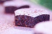 Rusty hexagonal bolt heads
  A phillips wood screw being driven into a board with a drill
  Combination flanged-hex/Phillips-head screw used in computers
(a) pan, (b) button, (c) round, (d) truss, (e) flat (countersunk), (f) oval
 Phillips vs. Frearson
  BNAE driver bit
  Hex socket screws
  Tamper-resistant external-TORX driver
  One-way slotted screw
An electric driver screws a self tapping phillips head screw into wood
 Screw making machine, 1871
Read More »»
A screw is a shaft with a helical groove or thread formed on its surface and provision at one end to turn the screw. Its main uses are as a threaded fastener used to hold objects together, and as a simple machine used to translate torque into linear force. It can also be defined as an inclined plane wrapped around a shaft.
Screws and Bolts
A screw used as a threaded fastener consists of a cylindrical shaft, which in many cases tapers to a point at one end, and with a helical ridge or thread formed on it, and a head at the other end which can be rotated by some means. The thread is essentially an inclined plane wrapped around the shaft. The thread mates with a complementary helix in the material. The material may be manufactured with the mating helix using a tap, or the screw may create it when first driven in (a self-tapping screw). The head is specially shaped to allow a screwdriver or wrench (British English: spanner) to rotate the screw, driving it in or releasing it. The head is of larger diameter than the body of the screw and has no thread so that the screw can not be driven deeper than the length of the shaft, and to provide compression.
Screws can normally be removed and reinserted without reducing their effectiveness. They have greater holding power than nails and permit disassembly and reuse.
The vast majority of screws are tightened by clockwise rotation; we speak of a right-hand thread. Screws with left-hand threads are used in exceptional cases, when the screw is subject to anticlockwise forces that might undo a right-hand thread. Left-hand screws are used on rotating items such as the left-hand grinding wheel on a bench grinder or the left hand pedal on a bicyclehub nuts on the left side of some automobiles. (both looking towards the equipment) or
Threaded fasteners were made by a cutting action such as dies provide, but recent advances in tooling allow them to be made by rolling an unthreaded rod (the blank) between two specially machined dies which squeeze the blank into the shape of the required fastener, including the thread. This method has the advantages of work hardening the thread and saving material. A rolled thread can be distinguished from a thread formed by a die as the outside diameter of the thread is greater than the diameter of the unthreaded portion of the shaft. Bicycle spokes, which are just bolts with long thin unthreaded portions, always use rolled threads for strength.
Differentiation between bolt and screw


A universally accepted distinction between a screw and a bolt does not exist.
In common usage the term screw refers to smaller (less than 1/4 inch) threaded fasteners, especially threaded fasteners with tapered shafts and the term bolt refers to larger threaded fasteners that do not have tapered shafts. The term machine screw is commonly used to refer to smaller threaded fasteners that do not have a tapered shaft.
Various methods of distinguishing bolts and screws exist or have existed. These methods conflict at times and can be confusing. Old SAE and USS standards made a distinction between a bolt and a cap screw based on whether a portion of the shaft was un-threaded or not. Cap screws had shafts that were threaded up to the head and bolts had partially threaded shafts. Today a bolt that has a completely threaded shaft might be referred to as a tap bolt.
ASME B18.2.1 defines a bolt as "an externally threaded fastener designed for insertion through the holes in assembled parts, and is normally intended to be tightened or released by torquing a nut". Using this definition to determine whether a particular threaded fastener is a screw or a bolt requires that an assumption be made about the intended purpose of the threaded fastener and as a practical matter doesn't seem to be followed by most threaded fastener manufacturers. It also conflicts with common usage such as the term, "head bolt", which is a threaded fastener that mates with a tapped hole in an engine block and is not intended to mate with a nut.
It is possible to find other distinctions than those described above, but regardless of the particular distinction favored by an individual or standards body the use of the term screw or bolt varies. More specific terms for threaded fastener types that include the word screw or boltmachine screw or carriage bolt) have more consistent usage and are the common way to specify a particular kind of fastener. (such as
The US government made an effort to formalize the difference between a bolt and a screw, because different tariffs apply to each. The document seems to have no significant effect on common usage and does not eliminate the ambiguous nature of the distinction for some fasteners. It is available here.
Other fastening methods
Alternative fasteners to screws and bolts are nails, rivets, roll pins, pinned shafts, welding, soldering, brazing, gluing (including taping).
Another option is the threaded insert. Examples include Helical Inserts [1] and Keensert [2].
Materials and strength
Screws and bolts are made in a wide range of materials, with steel being perhaps the most common, in many varieties. Where great resistance to weather or corrosion is required, stainless steel, titanium, brass, bronze, monel or silicon bronze may be used, or a coating such as brass, zinc or chromium applied. Electrolytic action from dissimilar metals can be prevented with aluminium screws for double-glazing tracks, for example. Some types of plastic, such as nylon or Teflon, can be threaded and used for fastening requiring moderate strength and great resistance to corrosion or for the purpose of electrical insulation. Even porcelain and glass can have molded screw threads that are used successfully in applications such as electrical line insulators and canning jars.
The same type of screw or bolt can be made in many different grades of material. For critical high-tensile-strength applications, low-grade bolts may fail, resulting in damage or injury. On SAE-standard bolts, a distinctive pattern of marking is impressed on the heads to allow inspection and validation of the strength of the bolt. However, low-cost counterfeit fasteners may be found with actual strength far less than indicated by the markings. Such inferior fasteners are a danger to life and property when used in aircraft, automobiles, heavy trucks, and similar critical applications. Gradings are indicated as markings, while grade 0 is the lowest, grade 10 is the highest. Here is the sequence of bolt strength and markings, from least to most. Grade 0, 1 and 2 bolts have no markings, grade 3 has 2 radial lines, grade 5 has 3, grade 6 has 4, grade 7 has 5, grade 8 has 6, grade 9 has 7, grade 10 has 8.
In some applications joints are designed so that the screw or bolt will intentionally fail before more expensive components. In this case replacing an existing fastener with a higher strength fastener can result in equipment damage. Thus it is generally good practice to replace fasteners with the same grade originally installed.
Mechanical analysis

Rotating screw and fixed trough
A screw or bolt is a specialized application of the inclined plane. The inclined plane, called its thread, is helically disposed around a cylinder or shaft. That thread usually either fits into a corresponding (negative or female) helical thread in a nut, or forms a corresponding helical cut in surrounding softer material as it is inserted. A simple screw, such as for fastening, is typically pointed, and thereby is commonly distinguished (in informal terminology) from a bolt or machine screw. Common screws, and usually bolts, have a head which may be mechanically driven or rotated, which usually serves as a stop, and may have an unthreaded shoulder portion beneath the head.
The technical analysis (see also statics, dynamics) to determine the pitch, thread profile, coefficient of friction (static and dynamic), and holding power of a screw or bolt is very similar to that performed to predict wedge behavior. Wedges are discussed in the article on simple machines.
Critical applications of screws and bolts will specify a torque that must be applied when driving it. The main concept is to tension the bolt, and compress parts being held together, creating a spring-like assembly. The stress thus introduced to the bolt is called a preload. When external forces try to separate the parts, the bolt experiences no strain unless the preload force is exceeded.
As long as the preload is never exceeded, the bolt or nut will never come loose (assuming the full strength of the bolt is used). If the full strength of the bolt is not used (for example, a steel bolt threaded into aluminium, then a thread-locking adhesive or insert may be used.
If the preload is exceeded during normal use, the joint will eventually fail. The preload is calculated as a percentage of the bolt's yield tensile strength, or the strength of the threads it goes into, or the compressive strength of the clamped layers (plates, washers, gaskets), whichever is least.
Tensile strength

Screws and bolts are usually in tension when properly fitted. In most applications they are not designed to bear large shear forces. For example, when two overlapping metal bars joined by a bolt are likely to be pulled apart longitudinally, the bolt must be tight enough so that the frictionfretting). For this type of application, high-strength steel bolts are used and should be tightened to a specified torque. between the two bars can overcome the longitudinal force. If the bars slip, then the bolt may be sheared in half, or friction between the bolt and slipping bars may erode and weaken the bolt (called
High-strength steel bolts usually have a hexagonal head with an ISO strength rating (called property class) stamped on the head. The property classes most often used are 5.8, 8.8, and 10.9. The number before the point is the tensile ultimate strength in MPa divided by 100. The number after the point is 10 times the ratio of tensile yield strength to tensile ultimate strength. For example, a property class 5.8 bolt has a nominal (minimum) tensile ultimate strength of 500 MPa, and a tensile yield strength of 0.8 times tensile ultimate strength or 0.8(500) = 400 MPa.
Tensile ultimate strength is the stress at which the bolt fails (breaks in half). Tensile yield strength is the stress at which the bolt will receive a permanent set (an elongation from which it will not recover when the force is removed) of 0.2 % offset strain. When elongating a fastener prior to reaching the yield point, the fastener is said to be operating in the elastic region; whereas elongation beyond the yield point is referred to as operating in the plastic region, since the fastener has suffered permanent plastic deformation.
Mild steel bolts have property class 4.6. High-strength steel bolts have property class 8.8 or above. An M10, property class 8.8 bolt can very safely hold a static tensile load of about 15 kN.
There is no method to measure the tension of a bolt already in place other than to tighten it and identify at which point the bolt starts moving. This is known as 're-torqueing'. An electronic torque wrench is used on the bolt under test, and the torque applied is constantly measured. When the bolt starts moving (tightening) the torque briefly drops sharply - this drop-off point is considered the measure of tension.
Types of screws and bolts
Threaded fasteners either have a tapered shaft or a non-tapered shaft. Fasteners with tapered shafts are designed to either be driven into a substrate directly or into a pilot hole in a substrate. Mating threads are formed in the substrate as these fasteners are driven in. Fasteners with a non-tapered shaft are designed to mate with a nut or to be driven into a tapped hole.

Fasteners with a tapered shaft (tapping screws)
- Screw - There is not a universally accepted definition of the word, screw. It generally refers to a smaller threaded fastener with a tapered shaft. See the Differentiation Between Bolt and Screw section above for a more detailed discussion.
- Wood Screw – Generally has an un-threaded portion of the shaft below the head. It is designed to attach two pieces of wood together.
- Lag Screw (Lag Bolt) – Similar to a wood screw except that it is generally much larger running to lengths up to 15 inches (381 mm) with diameters from a quarter inch to 1/2 inches (6.4 mm-12.25 mm) in commonly available (hardware store) sizes (not counting larger mining and civil engineering lags and lag bolts) and it generally has a hexagonal head drive head. Lag bolts are design for securely fastening heavy timbers (post and beams, timber railway trestles and bridges) to one another, or to fasten wood to masonry or concrete.
- Lag bolts are usually used with an expanding insert called a lag in masonry or concrete walls, the lag manufactured with a hard metal jacket that bites into the sides of the drilled hole, and the inner metal in the lag being a softer alloy of lead, or zinc amalgamated with soft iron. The coarse thread of a lag bolt and lag mesh and deform slightly making a secure near water tight anti-corroding mechanically strong fastening.
- Sheet Metal Screw (Self-tapping Screw, thread cutting screws) - Has sharp threads that cut into a material such as sheet metal, plastic or wood. They are sometimes notched at the tip to aid in chip removal during thread cutting. The shaft is usually threaded up to the head. Sheet metal screws make excellent fasteners for attaching metal hardware to wood because the fully thread shaft provides good retention in wood.
- Self-drilling screw (Teks(R) screw) - Similar to a sheet metal screw, but it has a drill-shaped point to cut through the substrate to eliminate the need for drilling a pilot hole. Designed for use in soft steel or other metals.
- Drywall screw - Specialized screw with a bugle head that is designed to attach drywall to wood or metal studs, however it is a versatile construction fastener with many uses. The diameter of drywall screw threads is larger than the shaft diameter.
- Particle Board Screw (Chipboard Screw) - Similar to a drywall screw except that it has a thinner shaft and provides better holding power in particle board.
- Deck Screw - Similar to drywall screw except that it is has improved corrosion resistance and is generally supplied in a larger gauge.
- Double ended screw (Dowel screw) - Similar to a wood screw but with two pointed ends and no head, used for making hidden joints between two pieces of wood.
- Screw Eye(Eye Screw) - Screw with a looped head. Larger ones are sometimes call lag eye screws. Designed to be used as attachment point, particularly for something that is hung from it.

Fasteners with a non-tapered shaft
- Bolt - There is no universally accepted definition of the word bolt. It generally refers to a larger threaded fastener with a non-tapered shaft. See the Differentiation Between Bolt and Screw section above for a more detailed discussion.
- Cap Screw – In places the term is used interchangeably with bolt. In the past the term, cap screw was restricted to threaded fasteners with a shaft that is threaded all the way to the head, however this is now a non-standard usage.
- Hex Cap Screw – Cap screw with a hexagonal head, designed to be driven by a wrench (spanner). An ASME B18.2.1 compliant cap screw has somewhat tighter tolerances than a hex bolt for the head height and the shaft length. The nature of the tolerance difference allows an ASME B18.2.1 hex cap screw to always fit where a hex bolt is installed but a hex bolt could be slightly too large to be used where a hex cap screw is designed in.
- Hex Bolt - At times the term is used interchangeably with hex cap screw. An ASME B18.2.1 compliant hex bolt is built to different tolerances than a hex cap screw.
- Socket Cap Screw – Also known as a socket head cap screw, socket screw or "Allen bolt," this is a type of cap screw with a hexagonal recessed drive. The most common types in use are fitted with a cylindrical head whose diameter is nominally 1.5 times (1960 series design) that of the screw shank (major) diameter. Other head designs include button head and flat head, the latter designed to be seated into countersunk holes. A hex keyhex driver is required to tighten or loosen a socket screw. Socket screws are commonly used in assemblies that do not provide sufficient clearance for a conventional wrench or socket. (sometimes referred to as an "Allen wrench") or
- Machine screw - Generally a smaller fastener (less than 1/4 inch in diameter) threaded the entire length of its shaft that usually has a recessed drive type (slotted, Phillips, etc.). Machine screws are also made with socket heads (see above), in which case they may be referred to as socket head machine screws.
- Self Tapping Machine Screw – Similar to a machine screw except the lower part of the shaft is designed to cut threads as the screw is driven into an un-tapped hole. The advantage of this screw type over a self tapping screw is that if the screw is reinstalled new threads are not cut as the screw is driven.
- Set screw (grub screw) - Generally a headless screw but can be any screw used to fix a rotating part to a shaft. The set screw is driven through a threaded hole in the rotating part until it is tight against the shaft. The most often used type is the socket set screw, which is tightened or loosened with a hex key or hex driver.
- Tap Bolt - A bolt that is threaded all the way to the head. An ASME B18.2.1 compliant tap bolt has the same tolerances as an ASME B18.2.1 compliant hex cap screw.
- Stud - similar to a bolt but without the head. Studs are threaded on both ends. In some cases the entire length of the stud is threaded, while in other cases there will be an un-threaded section in the middle. (See also: screw anchor, wedge anchor.)
- Eye Bolt – A bolt with a looped head.
- Toggle Bolt – A bolt with a special nut known as a wing. It is designed to be used where there is no access to side of the material where the nut is located. Usually the wing is spring loaded and expands after being inserted into the hole.
- Carriage Bolt (Coach Bolt) - Has a domed or countersunk head, and the shaft is topped by a short square section under the head. The square section grips into the part being fixed (typically wood), preventing the bolt from turning when the nut is tightened. A rib neck carriage bolt has several longitudinal ribs instead of the square section, to grip into a metal part being fixed.
- Stove Bolt - Similar to a carriage bolt, but usually used in metal. It requires a square hole in the metal being bolted to prevent the bolt from turning.
- Shoulder Screw - Screw used for revolving joints in mechanisms and linkages. A shoulder screw consists of the shaft, which is ground to a precise diameter, and a threaded end, which is smaller in diameter than the shaft. Unlike other threaded fasteners, the size of a shoulder screw is defined by the shaft diameter, not the thread diameter. Shoulder screws are also called stripper bolts, as they are often used as guides for the stripper plate(s) in a die set.
- Thumb Screw – A threaded fastener designed to be twisted into a tapped hole by hand without the use of tools.
- Tension Control Bolt (TC Bolt) – Heavy duty bolt used in steel frame construction. The head is usually domed and is not designed to be driven. The end of the shaft has a spline on it which is engaged by a special power wrench which prevents the bolt from turning while the nut is tightened. When the appropriate torque is reached the spline shears off.
Other threaded fasteners
- Thread rolling screws - have a lobed (usually triangular) cross section. They form threads by pushing outward during installation. They may have tapping threads or machine threads.
- Superbolt, or Multi-Jackbolt Tensioner Alternative type of fastener that retrofits or replaces existing nuts, bolts, or studs. Tension in the bolt is developed by torquing individual jackbolts which are threaded through the body of the nut and push against a hardened washer. Installation and removal of any size tensioner is achieved with hand tools, which can be advantageous when dealing with large diameter bolting applications.
- Hanger Screw – A headless fastener that has machine screw threads on one end and self tapping threads on the other designed to be driven into wood or another soft substrate. Often used for mounting legs on tables.
Shapes of screw head

(a) pan, (b) button, (c) round, (d) truss, (e) flat (countersunk), (f) oval
- pan head: a low disc with chamfered outer edge.
- button or dome head: cylindrical with a rounded top.
- round head: dome-shaped, commonly used for machine screws.
- truss head: lower-profile dome designed to prevent tampering.
- flat head or countersunk: conical, with flat outer face and tapering inner face allowing it to sink into the material.
- oval or raised head: countersunk with a rounded top.
- bugle head: similar to countersunk, but there is a smooth progression from the shaft to the angle of the head, similar to the bell of a bugle.
- cheese head: disc with cylindrical outer edge, height approximately half the head diameter.
- fillister head: cylindrical, but with a slightly convex top surface.
- socket head: cylindrical, relatively high, with different types of sockets (hex, square, torx, etc.).
- mirror screw head: countersunk head with a tapped hole to receive a separate screw-in chrome-plated cover, used for attaching mirrors.
- headless (set or grub screw): has either a socket or slot in one end for driving.
Some varieties of screw are manufactured with a break-away head, which snaps off when adequate torque is applied. This prevents tampering and disassembly and also provides an easily-inspectable joint to guarantee proper assembly.
Types of screw drive
| Part of the series on | |
|---|---|
| Screw drive types | |
| | Slotted |
| | Phillips ("Crosshead") |
| | Pozidriv (SupaDriv) |
| | Torx |
| | Hex (Allen) |
| | Robertson |
| | Tri-Wing |
| | Torq-Set |
| | Spanner Head |
| | Triple Square (XZN) |
| | Polydrive |
| | One-way |
| Others: | |
| spline drive, double hex | |


Modern screws employ a wide variety of drive designs, each requiring a different kind of tool to drive in or extract them. The most common screw drives are the slotted and Phillips; hex, Robertson, and TORX are also common in some applications. Some types of drive are intended for automatic assembly in mass-production of such items as automobiles. More exotic screw drive types may be used in situations where tampering is undesirable, such as in electronic appliances that should not be serviced by the home repair person.
- Slot head has a single slot, and is driven by a flat-bladed screwdriver. The slotted screw is common in woodworking applications, but is not often seen in applications where a power driver would be used, due to the tendency of a power driver to slip out of the head and potentially damage the surrounding material.
- Cross-head, cross-point, or cruciform has a "+"-shaped slot and is driven by a cross-head screwdriver, designed originally for use with mechanical screwing machines. There are five types:
- The Phillips screw drive has slightly rounded corners in the tool recess, and was designed so the driver will slip out, or cam out, under high torque to prevent over-tightening. The Phillips Screw Company was founded in Oregon in 1933 by Henry F. Phillips, who bought the design from J. P. Thompson. Phillips was unable to manufacture the design, so he passed the patent to the American Screw Company, who was the first to manufacture it.
- A Reed & Prince or Frearson screw drive is similar to a Phillips but has a more pointed 75° V shape. Its advantage over the Phillips drive is that one driver or bit fits all screw sizes. It is found mainly in marine hardware and requires a special screw driver or bit to work properly. The tool recess is a perfect cross, unlike the Phillips head, which is designed to cam out. It was developed by an English inventor named Frearson in the 19th century and produced from the late 1930s to the mid-1970s by the former Reed & Prince Manufacturing Company of Worcester, Massachusetts, a company which traces its origins to Kingston, Massachusetts, in 1882, and was liquidated in 1990 with the sale of company assets. The company is now in business.
- A JIS (Japanese Industrial Standard) head, commonly found in Japanese equipment, looks like a Phillips screw, but is designed not to cam out and will, therefore, be damaged by a Phillips screwdriver if it is too tight. Heads are usually identifiable by a single dot to one side of the cross slot. The standard number is JIS B 1012:1985
- French Recess, also called BNAE NFL22-070 for Bureau de Normalisation de l'Aéronautique et de l'Espace, a French standards organization.
- Pozidriv is patented, similar to cross-head but designed not to slip, or cam out. It has four additional points of contact, and does not have the rounded corners that the Phillips screw drive has. Phillips screwdrivers will usually work in Pozidriv screws, but Pozidriv screwdrivers are likely to slip or tear out the screw head when used in Phillips screws. Heads are marked with single lines at 45 degrees to the cross recess, for identification. (note that two lines at 45 are a different recess: a very specialised Phillips screw). Pozidriv was jointly patented by the Phillips Screw Company and American Screw Company in the USA. Developed by GKN in the 1960s, the recess is licenced from Trifast PLC in the rest of the world.
- Supadriv is similar to Pozidriv.
- TORX is a star-shaped "hexalobular" drive with six rounded points. It was designed to permit increased torque transfer from the driver to the bit compared to other drive systems. TORX is very popular in the automotive and electronics industries due to resistance to cam out and extended bit life, as well as reduced operator fatigue by minimizing the need to bear down on the drive tool to prevent cam out. TORX screws were found in early Apple Macintosh computers, to discourage home repairs[citation needed]. TORX PLUS is an improved version of TORX which extends tool life even further and permits greater torque transfer compared to TORX. A tamper-resistant TORX head has a small pin inside the recess. The tamper-resistant TORX is also made in a 5 lobed variant. These "5-star" TORX configurations are commonly used in correctional facilities, public facilities and government schools, but can also be found in some electronic devices, such as Seagate's external drives.
- TTAP is an improved "hexalobular" drive for without wobbling and stable stick-fit. TTAP is backward convertible with generic hexalobular drive.

- Hexagonal (hex) socket head has a hexagonal hole and is driven by a Hex Wrench, sometimes called an Allen key or Hex key, or by a power tool with a hexagonal bit. Tamper-resistant versions with a pin in the recess are available. Hex sockets are increasingly used for modern bicycle parts because hex wrenches are very light and easily carried tools. They are also frequently used for self-assembled furniture.
- Robertson head, invented in 1908 by P.L. Robertson, has a square hole and is driven by a special power-tool bit or screwdriver. The screw is designed to maximize torque transferred from the driver, and will not slip, or cam out. It is possible to hold a Robertson screw on a driver bit horizontally or even pendant, due to a slight wedge fit. Commonly found in Canada in carpentry and woodworking applications and in Canadian-manufactured electrical wiring items such as receptacles and switch boxes.
- Square-drive head is an American clone of the Robertson that has a square hole without taper. Due to the lack of taper, the hole must be oversize relative to the screwdriver, and is much more likely to strip than the Robertson.
- Tri-Wing head has a triangular slotted configuration. They were used by Nintendo on several consoles and accessories, including the Game Boy, Wii, and Wii Remote, and on some Nokia phones and chargers to discourage home repair.
- Torq-Set or offset cruciform may be confused with Phillips; however, the four legs of the contact area are offset in this drive type. Is commonly used in the aerospace industry.
- Spanner drive uses two round holes opposite each other, and is designed to prevent tampering. Commonly seen in elevators in the United States.
- Clutch Type A or standard clutch head resembles a bow tie. These were common in GM automobiles, trucks and buses of the 1940s and 1950s, particularly for body panels.
- Clutch Type G head resembles a butterfly. This type of screw head is commonly used in the manufacture of mobile homes and recreational vehicles.
Combination drives
Some screws have heads designed to accommodate more than one kind of driver, sometimes referred to as combo-head or combi-head. The most common of these is a combination of a slotted and Phillips head, often used in attaching knobs to furniture drawer fronts. Because of its prevalence, there are now drivers made specifically for this kind of screw head. Other combinations are a Phillips and Robertson, a Robertson and a slotted, a Torx and a slotted, and a triple-drive screw which can take a slotted, Phillips or a Robertson. The Recex drive system claims it offers the combined non-slip convenience of a Robertson drive during production assembly and Phillips for after market serviceability. Quadrex is another Phillips/Robertson drive. Phillips Screw Company offers both Phillips and Pozidriv(sic) combo heads with Robertson.
Tamper-resistant screws


Many screw drives, including Phillips, TORX, and Hexagonal, are also manufactured in tamper-resistant form. These typically have a pin protruding in the center of the screw head, necessitating a special tool for extraction. In some variants the pin is placed slightly off-center, requiring a correspondingly shaped bit. However, the bits for many tamper-resistant screw heads are now readily available from hardware stores, tool suppliers and through the Internet. What is more, there are many commonly used techniques to extract tamper resistant screws without the correct driver — for example, the use of an alternative driver that can achieve enough grip to turn the screw, modifying the head to accept an alternative driver, forming ones own driver by melting an object into the head to mould a driver, or simply turning the screw using a pair of locking pliers. Thus, these special screws offer only modest security.
The slotted screw drive also comes in a tamper-resistant one-way design with sloped edges; the screw can be driven in, but the bit slips out in the reverse direction.
There are specialty fastener companies that make unusual, proprietary head designs, featuring matching drivers available only from them, and only supplied to registered owners[1]. An example of this would be the attachment for the wheels and/or spare tires of some types of car; one of the nuts may require a specialized socket (provided with the car) to prevent theft.
The break away bolt is a high security fastener that is extremely difficult to remove. It consists of a counter-sunk flat head screw, with a thin shaft and hex head protruding from the flat head. The hex head is used to drive the bolt into the countersunk hole, then the wrench or hammer is used to knock the shaft and hex head off of the flat head, leaving only a smooth screw head exposed. Removal is facilitated by drilling a small hole part way into the outer part of the head and using a punch and hammer at a sharp angle in a counter-clockwise direction. This type of screw is used primarily in prison door locks.
Tools used
The hand tool used to drive in most screws is called a screwdriver. A power tool that does the same job is a power screwdriver; power drills may also be used with screw-driving attachments. Where the holding power of the screwed joint is critical, torque-measuring and torque-limiting screwdrivers are used to ensure sufficient but not excessive force is developed by the screw. The hand tool for driving cap screws and other types is called a spanner (UK usage) or wrench (US usage).
Mechanics of use
When driving in a screw, especially when the screw has been removed and is being placed again, the threads can become misaligned and damage, or strip, the threading of the hole. To avoid this, slight pressure is applied and the screw is driven in reverse, until the leading edges of the helices pass each other, at which point a slight click will be felt (and sometimes heard.) When this happens, the screw will often assume a more aligned position with respect to the hole.
Immediately after the 'click', the screw may be driven in without damage to the threading. This technique is useful for re-seating screws in wood and plastic, and for assuring the proper fit when screwing down plates and covers where alignment is difficult.
Thread standards
See also: Screw thread
There are many systems for specifying the dimensions of screws, but in much of the world the ISO metric screw thread preferred series has displaced the many older systems. Other relatively common systems include the British Standard Whitworth, BA system (British Association), and the SAE Unified Thread Standard.
[edit] ISO metric screw thread
The basic principles of the ISO metric screw thread are defined in international standard ISO 68-1 and preferred combinations of diameter and pitch are listed in ISO 261. The smaller subset of diameter and pitch combinations commonly used in screws, nuts and bolts is given in ISO 262. The most commonly used pitch value for each diameter is known as the "coarse pitch". For some diameters, one or two additional "fine pitch" variants are also specified, for special applications such as threads in thin-walled pipes. ISO metric screw threads are designated by the letter Mmultiplication sign, e.g. "M8×1" if the screw thread has an outer diameter of 8 mm and advances by 1 mm per 360° rotation. followed by the major diameter of the thread in millimeters, e.g. "M8". If the thread does not use the normal "coarse pitch" (e.g., 1.25 mm in the case of M8), then the pitch in millimeters is also appended with a
The nominal diameter of a metric screw is the outer diameter of the thread. The tapped hole (or nut) into which the screw fits, has an internal diameter which is the size of the screw minus the pitch of the thread. Thus, an M6 screw, which has a pitch of 1 mm, is made by threading a 6 mm shaft, and the nut or threaded hole is made by tapping threads in a 5 mm hole.
Metric hexagon bolts, screws and nuts are specified, for example, in British Standard BS 4190 (general purpose screws) and BS 3692 (precision screws). The following table lists the relationship given in these standards between the thread size and the maximal width across the hexagonal flats (wrench size):
| ISO metric thread | M1.6 | M2 | M2.5 | M3 | M4 | M5 | M6 | M8 | M10 | M12 | M16 | M20 | M24 | M30 | M36 | M42 | M48 | M56 | M64 |
|---|---|---|---|---|---|---|---|---|---|---|---|---|---|---|---|---|---|---|---|
| wrench size (mm) | 3.2 | 4 | 5 | 5.5 | 7 | 8 | 10 | 13 | 17 | 19 | 24 | 30 | 36 | 46 | 55 | 65 | 75 | 85 | 95 |
In addition, the following non-preferred intermediate sizes are specified:
| ISO metric thread | M14 | M18 | M22 | M27 | M33 | M39 | M45 | M52 | M60 | M68 |
|---|---|---|---|---|---|---|---|---|---|---|
| wrench size (mm) | 22 | 27 | 32 | 41 | 50 | 60 | 70 | 80 | 90 | 100 |
Whitworth
The first person to create a standard (in about 1841) was the English engineer Sir Joseph Whitworth. Whitworth screw sizes are still used, both for repairing old machinery and where a coarser thread than the metric fastener thread is required. Whitworth became British Standard Whitworth, abbreviated to BSW (BS 84:1956) and the British Standard Fine (BSF) thread was introduced in 1908 because the Whitworth thread was a bit coarse for some applications. The thread angle was 55° and a depth and pitch of thread that varied with the diameter of the thread (i.e., the bigger the bolt, the coarser the thread). The spanner size is determined by the size of the bolt, not the distance between the flats.
The most common use of a Whitworth pitch nowadays is in all (UK) scaffolding where a 7/16" spanner size is required. A 21mm spanner is frequently used, and works for this application. Additionally, the standard photographic tripod thread, which for small cameras is 1/4" Whitworth (20 tpi) and for medium/large format cameras is 3/8" Whitworth (16 tpi). It is also used for microphone stands and their appropriate clips, again in both sizes, along with "thread adapters" to allow the smaller size to attach to items requiring the larger thread.
British Association screw threads (BA)
A later standard established in the United Kingdom was the BA system, named after the British Association for Advancement of Science. Screws were described as "2BA", "4BA" etc., the odd numbers being rarely used, except in equipment made prior to the 1970's for telephone exchanges in the UK. This equipment made extensive use of odd-numbered BA screws, in order -- it may be suspected -- to reduce theft. While not related to ISO metric screws, the sizes were actually defined in metric terms, a 0BA thread having a 1 mm pitch. These are still the most common threads in some niche applications. Certain types of fine machinery, such as moving-coil meters, tend to have BA threads wherever they are manufactured.
Unified Thread Standard
The United States of America has its own system, usually called the Unified Thread Standard, which is also extensively used in Canada and in most other countries around the world. At least 85% of the world's fasteners are dimensioned to Unified thread dimensions, and the biggest selection of fastener sizes and materials are found supplied in this standard.[2] A version of this standard, called SAE for the Society of Automotive Engineers, was used in the American automobile industry. The SAE is still associated with inch-based fasteners by the public, even though the U.S. auto industry (and other heavy industries relying on SAE) have gradually converted to ISO preferred series fasteners for some assemblies from the 1970s onward, because global parts sourcing and product marketing favor international standardization. However, all automobiles sold throughout the world contain both metric (engine assemblies) and Imperial fasteners (for example, lug nuts, oxygen sensors, internal electrical assemblies, body fasteners, lamps, steering, brake and suspension parts).
Machine screws are described as 0-80, 2-56, 3-48, 4-40, 5-40, 6-32, 8-32, 10-32, 10-24, etc. up to size 16. The first number can be translated to a diameter using a formula, the second is the number of threads per inch. There is a coarse thread and a fine thread for each size, the fine thread being preferred in thin materials or when slightly greater strength is desired.
The numbering system follows a roughly logarithmic series where an increase in each screw number size approximately doubles the tensile strength of the screw and the screw number is found by 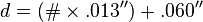 , where "d" is the nominal diameter. Using this formula a #5 screw has a major diameter of .125" (1/8"), a #10 screw has a diameter of .190" (or 3/16" in practical terms), etc. The formula applies for screw thread numbers #0 and higher, but does NOT apply to smaller Unified miniature screw thread series. Typically screws smaller than size #0 are supplied in the Unified Miniature Series. The formula for number sizes smaller than size #0 is given by
  , with the zero size being the number of zeros after the first. So a #00 screw is .047" dia, #000 is .034" dia, etc.
The number series of machine screws once included odd numbers (7, 9, etc.) and extended up to #16 or more. Standardization efforts in the late 19th and the early part of the 20th century reduced the range of sizes considerably. Now, it is less common to see machine screws larger than #14, or odd number sizes other than #1, #3 and #5. Even though #14 and #16 screws are still available, they are not as common as sizes #0 through #12.
Sizes 1/4" diameter and larger are designated as 1/4"-20, 1/4"-28, etc. the first number giving the diameter in inches and the second number being threads per inch. Most thread sizes are available in UNC or UC (Unified Coarse Thread, example 1/4"-20) or UNF or UF (Unified Fine Thread, example 1/4"-28).
Others
Other thread systems include Acme thread form, BSP (British standard pipe thread which exists in a taper and non taper variant; used for other purposes as well) and BSC (British Standard Cycle) a 26tpi thread form, CEI (Cycle Engineers Institute, used on bicycles in Britain and possibly elsewhere), British Standard Brass a fixed pitch 26tpi thread, NPT (National Pipe Thread) and NPTF (National Pipe Thread Fuel), and PG (German: "Panzer-Gewinde"), used in thin plate metal, such as for switches and nipples in electrical equipment housings.
History

In antiquity, the screw was first used as part of the screw pump of Sennacherib, King of Assyria, for the water systems at the Hanging Gardens of Babylon and Nineveh in the 7th century BC.[3]
The screw was later described by the Greek mathematician Archytas of Tarentum (428 – 350 BC). By the 1st century BC, wooden screws were commonly used throughout the Mediterraneanoil and wine presses. Metal screws used as fasteners did not appear in Europe until the 1400s. world in devices such as
The metal screw did not become a common woodworking fastener until machine tools for mass production were developed at the end of the eighteenth century. In 1770, English instrument maker, Jesse Ramsden (1735-1800) invented the first satisfactory screw-cutting lathe. The British engineer Henry Maudslay (1771-1831) patented a screw-cutting lathe in 1797; a similar device was patented by David Wilkinson in the United States in 1798.
In 1908, square-drive screws were invented by Canadian P. L. Robertson, becoming a North American standard. In the early 1930s, the Phillips head screw was invented by Henry F. Phillips.
Standardization of screw thread forms accelerated during WWII so that interchangeable parts could be produced by any of the Allied countries.
Prior to the mid nineteenth century, cotter pins or pin bolts, and "clinch bolts" (now called rivets), were used in ship building.
In 1744, the flat-bladed bit for the carpenter's brace was invented, the precursor to the first simple screwdriver. Handheld screwdrivers first appeared after 1800.
Legal issues
In the United States a screw and a bolt have different import duties. The difference between them is therefore of keen interest to importers and customs authorities.
This was the subject of a court case Rocknel Fastener, inc v. United States: 34 page PDF. The position is outlined in a current US government document Distinguishing Bolts From Screws: 21 page PDF.
Subscribe to:
Posts (Atom)
